Almera Tino V10 (2003 year). Manual - part 48
YBR329A
GI
MA
EM
LC
EC
FE
CL
MT
AT
AX
SU
ST
RS
BT
HA
SC
EL
IDX
DESCRIPTION
ABS
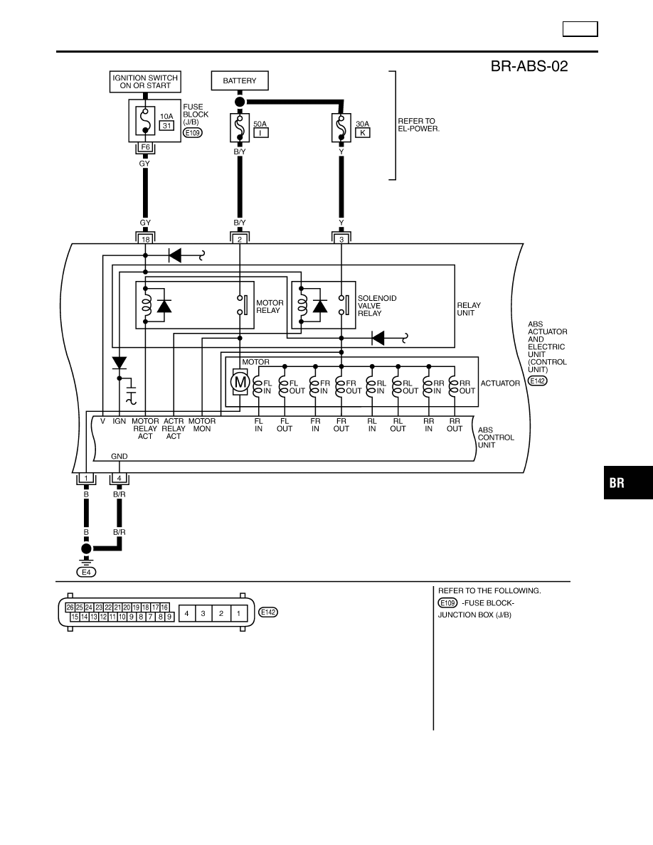
Wiring Diagram — ABS — (Cont’d)
BR-51
|
|
|
YBR329A GI MA EM LC EC FE CL MT AT AX SU ST RS BT HA SC EL IDX DESCRIPTION ABS Wiring Diagram — ABS — (Cont’d) BR-51 |