Almera Tino V10 (2003 year). Manual - part 40
TROUBLE DIAGNOSIS
ATC-97
C
D
E
F
G
H
I
K
L
M
A
B
ATC
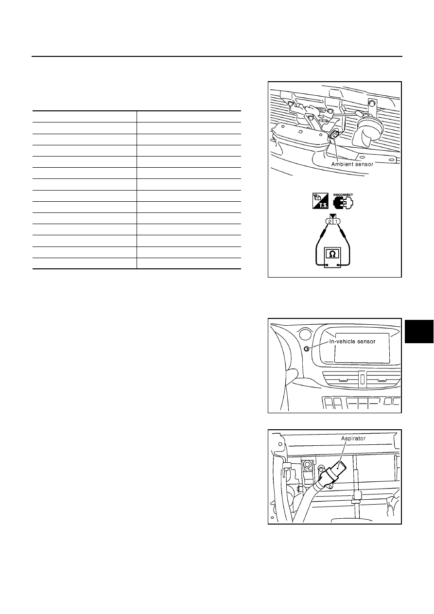
COMPONENT INSPECTION
Ambient Sensor
After disconnecting ambient sensor harness connector, measure
resistance between terminals 2 and 1 at sensor harness side, using
the table below.
If NG, replace ambient sensor.
In-vehicle Sensor Circuit
EJS0037H
COMPONENT DESCRIPTION
In-vehicle sensor
The in-vehicle sensor is located on instrument lower panel. It con-
verts variations in temperature of compartment air drawn from the
aspirator into a resistance value. It is then input into the auto ampli-
fier.
Aspirator
The aspirator is located on heater & cooling unit. It produces vacuum
pressure due to air discharged from the heater & cooling unit, contin-
uously taking compartment air in the aspirator.
Temperature
°
C (
°
F)
Resistance k
Ω
−
15 (5)
12.73
−
10 (14)
9.92
−
5 (23)
7.80
0 (32)
6.19
5 (41)
4.95
10 (50)
3.99
15 (59)
3.24
20 (68)
2.65
25 (77)
2.19
30 (86)
1.81
35 (95)
1.51
40 (104)
1.27
45 (113)
1.07
RJIA2327E
RJIA2328E
RHA650H