Almera Tino V10 (2003 year). Manual - part 35


  Index      Manuals     Almera Tino V10 (2003 year) - Service and Repair Manual


Search            copyright infringement  


Content      ..     33      34      35      36     ..


Almera Tino V10 (2003 year). Manual - part 35


REFRIGERATION SYSTEM

ATC-17

C

D

E

F

G

H

I

K

L

M

A

B

ATC

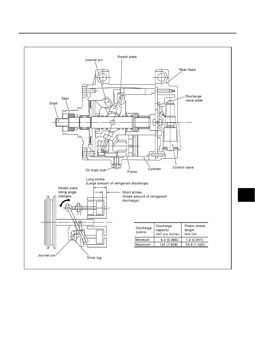
The tilt of the swash plate allows the piston

s stroke to change so that refrigerant discharge can be continu-

ously changed from 6.0 to 125 cm

3

(0.366 to 7.628 cu. in).

Operation

1.

Operation Control Valve
Operation control valve is located in the suction port (low-pressure) side, and opens or closes in response
to changes in refrigerant suction pressure.
Operation of the valve controls the internal pressure of the crankcase.
The angle of the swash plate is controlled between the crankcase

s internal pressure and the piston cylin-

der pressure.

2.

Maximum Cooling
Refrigerant pressure on the low–pressure side increases with an increase in heat loads.
When this occurs, the control valve

s bellows compress to open the low-pressure side valve and close the

high-pressure side valve.
This causes the following pressure changes:

The crankcase

s internal pressure to equal the pressure on the low-pressure side;

RHA854HA

ATC-18

REFRIGERATION SYSTEM

The cylinder

s internal pressure to be greater than the crankcase

s internal pressure.

Under this condition, the swash plate is set to the maximum stroke position.

3.

Capacity Control

Refrigerant pressure on suction side is low during high speed driving or when ambient or interior tem-

perature is low.

The bellows expands when refrigerant pressure on the suction pressure side drops below approxi-

mately 177 kPa (1.77 bar, 1.8 kg/cm

2

, 26 psi).

Since suction pressure is low, it makes the suction port close and the discharge port open. Thus, crank-
case pressure becomes high as high pressure enters the crankcase.

The force acts around the journal pin near the swash plate, and is generated by the pressure difference

before and behind the piston.
The drive lug and journal pin are located where the piston generates the highest pressure. Piston pres-
sure is between suction pressure Ps and discharge pressure Pd, which is near suction pressure Ps. If
crankcase pressure Pc rises due to capacity control, the force around the journal pin makes the swash
plate angle decrease and also the piston stroke decrease. In other words, crankcase pressure increase
triggers pressure difference between the piston and the crankcase. The pressure difference changes the
angle of the swash plate.

RHA473C

RHA474C

REFRIGERATION SYSTEM

ATC-19

C

D

E

F

G

H

I

K

L

M

A

B

ATC

Component Layout

EJS002ZV

NHA367

ATC-20

LUBRICANT

LUBRICANT

PFP:KLG00

Maintenance of Lubricant Quantity in Compressor

EJS002ZW

The lubricant in the compressor circulates through the system with the refrigerant. Add lubricant to compres-
sor when replacing any component or after a large gas leakage occurred. It is important to maintain the speci-
fied amount.
If lubricant quantity is not maintained properly, the following malfunctions may result:

Lack of lubricant: May lead to a seized compressor

Excessive lubricant: Inadequate cooling (thermal exchange interference)

LUBRICANT

LUBRICANT RETURN OPERATION

Adjust the lubricant quantity according to the test group shown below.

1.

CHECK LUBRICANT RETURN OPERATION

Can lubricant return operation be performed?

A/C system works properly.

There is no evidence of a large amount of lubricant leakage.

Yes or No

Yes

>> GO TO 2.

No

>> GO TO 3.

2.

PERFORM LUBRICANT RETURN OPERATION, PROCEEDING AS FOLLOWS:

1.

Start engine, and set the following conditions:

Test condition
Engine speed: Idling to 1,200 rpm
A/C or AUTO switch: ON
Blower speed: Max. position
Temp. control: Optional [Set so that intake air temperature is 25 to 30

°

C (77 to 86

°

F).]

Intake position: Recirculation (REC)

2.

Perform lubricant return operation for about 10 minutes.

3.

Stop engine.

CAUTION:

If excessive lubricant leakage is noted, do not perform the lubricant return operation.

>> GO TO 3.

3.

CHECK COMPRESSOR

Should the compressor be replaced?

Yes or No

Yes

>> Go to

ATC-21, "LUBRICANT ADJUSTING PROCEDURE FOR COMPRESSOR REPLACE-

MENT"

.

No

>> GO TO 4.

Name:

Nissan A/C System Oil Type S

Part number:

KLH00-PAGS0

LUBRICANT

ATC-21

C

D

E

F

G

H

I

K

L

M

A

B

ATC

4.

CHECK ANY PART

Is there any part to be replaced? (Evaporator, condenser, liquid tank or in case there is evidence of a large
amount of lubricant leakage.)

Yes or No

Yes

>> Go to

ATC-21, "LUBRICANT ADJUSTING PROCEDURE FOR COMPONENTS REPLACEMENT

EXCEPT COMPRESSOR"

.

No

>> Carry out the A/C performance test.

LUBRICANT ADJUSTING PROCEDURE FOR COMPONENTS REPLACEMENT EXCEPT COM-
PRESSOR

After replacing any of the following major components, add the correct amount of lubricant to the system.
Amount of lubricant to be added

*1:If refrigerant leak is small, no addition of lubricant is needed.

LUBRICANT ADJUSTING PROCEDURE FOR COMPRESSOR REPLACEMENT

1.

Before connecting ACR4 to vehicle, check ACR4 gauges. No refrigerant pressure should be displayed. If
NG, recover refrigerant from equipment lines.

2.

Discharge refrigerant into the refrigerant recovery/recycling equipment. Measure lubricant discharged into
the recovery/recycling equipment.

3.

Drain the lubricant from the old (removed) compressor into a graduated container and recover the amount
of lubricant drained.

4.

Drain the lubricant from the new compressor into a separate, clean container.

5.

Measure an amount of new lubricant installed equal to amount drained from old compressor. Add this
lubricant to new compressor through the suction port opening.

6.

Measure an amount of new lubricant equal to the amount recovered during discharging. Add this lubricant
to new compressor through the suction port opening.

7.

If the liquid tank also needs to be replaced, add an additional 5 m

(0.2 Imp fl oz.) of lubricant at this time.

Do not add this 5 m

(0.2 Imp fl oz.) of lubricant if only replacing the compressor.

Part replaced

Lubricant to be added to system

Remarks

Amount of lubricant

m

(Imp fl oz.)

Evaporator

75 (2.6)

-

Condenser

35 (1.2)

-

Liquid tank

10 (0.4)

-

In case of refrigerant leak

30 (1.1)

Large leak

-

Small leak *1

ATC-22

AIR CONDITIONER CONTROL

AIR CONDITIONER CONTROL

PFP:27500

Overview Air Conditioner LAN Control System

EJS002ZX

The LAN system consists of auto amp., mode door motor, air mix door motor and intake door motor.
A configuration of these components is shown in the diagram below.

System Construction

EJS002ZY

A small network is constructed between the auto amplifier, air mix door motor, mode door motor and intake
door motor. The auto amplifier and motors are connected by data transmission lines and motor power supply
lines. The LAN network is built through the ground circuits of the three motors.
Addresses, motor opening angle signals, motor stop signals and error checking messages are all transmitted
through the data transmission lines connecting the auto amplifier and three motors.
The following functions are contained in LCUs built into the air mix door motor, mode door motor and intake
door motor.

Address

Motor opening angle signals

Data transmission

Motor stop and drive decision

Opening angle sensor (PBR function)

Comparison

Decision (Auto amplifier indicated value and motor opening angle comparison)

OPERATION

The auto amplifier receives data from each of the sensors. The amplifier sends mode door, air mix door and
intake door opening angle data to the mode door motor LCU, air mix door motor LCU and intake door motor
LCU.
The mode door motor, air mix door motor and intake door motor read their respective signals according to the
address signal. Opening angle indication signals received from the auto amplifier and each of the motor posi-
tion sensors are compared by the LCUs in each motor with the existing decision and opening angles. Subse-
quently, HOT/COLD, DEFROST/VENT or FRESH/RECIRCULATION operation is selected. The new selection
data is returned to the auto amplifier.

RJIA0480E

RHA350H

AIR CONDITIONER CONTROL

ATC-23

C

D

E

F

G

H

I

K

L

M

A

B

ATC

TRANSMISSION DATA AND TRANSMISSION ORDER

Amplifier data is transmitted consecutively to each of the door motors following the form shown in figure below.
Start: Initial compulsory signal sent to each of the door motors.
Address: Data sent from the auto amplifier is selected according to data-based decisions made by the air mix
door motor, mode door motor and intake door motor.
If the addresses are identical, the opening angle data and error check signals are received by the door motor
LCUs. The LCUs then make the appropriate error decision. If the opening angle data is usual, door control
begins.
If an error exists, the received data is rejected and corrected data received. Finally, door control is based upon
the corrected opening angle data.
Opening angle:
Data that shows the indicated door opening angle of each door motor.
Error check:
Procedure by which sent and received data is checked for errors. Error data is then compiled. The error check
prevents corrupted data from being used by the air mix door motor, mode door motor and intake door motor.
Error data can be related to the following problems.

Unusual electrical frequency

Poor electrical connections

Signal leakage from transmission lines

Signal level fluctuation

Stop signal:
At the end of each transmission, a stop operation, in-operation, or internal problem message is delivered to
the auto amplifier. This completes one data transmission and control cycle.

AIR MIX DOOR CONTROL (AUTOMATIC TEMPERATURE CONTROL)

The air mix door is automatically controlled so that in-vehicle temperature is maintained at a predetermined
value by: The temperature setting, ambient temperature, in-vehicle temperature and amount of sunload.

RHA351H

RHA352H

ATC-24

AIR CONDITIONER CONTROL

FAN SPEED CONTROL

Blower speed is automatically controlled based on temperature setting, ambient temperature, in-vehicle tem-
perature, intake temperature, amount of sunload and air mix door position.
With FAN switch set to AUTO, the blower motor starts to gradually increase air flow volume.
When engine coolant temperature is low, the blower motor operation is delayed to prevent cool air from flow-
ing.

INTAKE DOOR CONTROL

The intake doors are automatically controlled by: The temperature setting, ambient temperature, in-vehicle
temperature, intake temperature, amount of sunload and ON-OFF operation of the compressor.

OUTLET DOOR CONTROL

The outlet door is automatically controlled by: The temperature setting, ambient temperature, in-vehicle tem-
perature, intake temperature and amount of sunload.

MAGNET CLUTCH CONTROL

The ECM controls compressor operation using input signals from the refrigerant pressure sensor (with QG
engine), throttle position sensor and auto amplifier.

SELF-DIAGNOSTIC SYSTEM

The self-diagnostic system is built into the auto amplifier (LCU) to quickly locate the cause of malfunctions.

Overview of Control system

EJS002ZZ

The control system consists of input sensors, switches, the automatic amplifier (microcomputer) and outputs.
The relationship of these components is shown in the diagram below:

RJIA0687E

AIR CONDITIONER CONTROL

ATC-25

C

D

E

F

G

H

I

K

L

M

A

B

ATC

Control Operation

EJS00300

DISPLAY SCREEN

Displays the operational status of the system.

AUTO SWITCH

The compressor, intake doors, air mix doors, outlet doors and blower speed are automatically controlled so
that the in-vehicle temperature will reach, and be maintained at the set temperature selected by the operator.

TEMPERATURE DIAL (POTENTIO TEMPERATURE CONTROL)

Increase or decrease the set temperature.

A/C SWITCH

The compressor is ON or OFF.
(Pressing the A/C switch when the AUTO switch is ON will turn off the A/C switch and compressor.)

DEFROSTER (DEF) SWITCH

Positions the air outlet doors to the defrost position. Also positions the intake doors to the outside air position.

MODE SWITCH

Control the air discharge outlets.

FAN SWITCH

Manually controls the blower speed. Five speeds are available for manual control (as shown on the display
screen).

OFF SWITCH

The compressor and blower are OFF, the intake doors are set to the outside air position, and the air outlet
doors are set to the foot position.

FRESH (FRE) SWITCH

OFF position: Interior air is recirculated inside the vehicle.
ON position: Outside air is drawn into the passenger compartment.
(When RECIRCULATION switch is ON, the FRESH switch turns OFF automatically.)

RJIA1675E

ATC-26

AIR CONDITIONER CONTROL

RECIRCULATION (REC) SWITCH

OFF position: Outside air is drawn into the passenger compartment.
ON position: Interior air is drawn into the passenger compartment.
(When the FRESH switch is ON or the compressor is turned from ON to OFF, the RECIRCULATION switch
turns OFF automatically.)

REAR WINDOW DEFOGGER SWITCH

When illumination is ON, rear window is defogged.

Fail-safe Function

EJS00301

If fail-safe request signal is sent from AV control unit, or if communication error exists between auto amplifier
and AV control unit for at least 30 seconds, air conditioner is controlled under following conditions.

Compressor

: ON

Air inlet

: Fresh

Air outlet

: AUTO

Blower fan speed

: AUTO

Set temperature

: Setting before communication error occurs

AIR CONDITIONER CONTROL

ATC-27

C

D

E

F

G

H

I

K

L

M

A

B

ATC

Discharge Air Flow

EJS00302

NHA371

ATC-28

AIR CONDITIONER CONTROL

System Description

EJS00303

SWITCHES AND THEIR CONTROL FUNCTION

RHA592H

RJIA1677E

TROUBLE DIAGNOSIS

ATC-29

C

D

E

F

G

H

I

K

L

M

A

B

ATC

TROUBLE DIAGNOSIS

PFP:00004

How to Perform Trouble Diagnoses for Quick and Accurate Repair

EJS00304

WORK FLOW

SYMPTOM TABLE

*1

ATC-50, "Operational Check"

SHA900E

Symptom

Reference Page

A/C system does not come on.

Go to Trouble Diagnosis Procedure for A/C System.

ATC-54, "Power

Supply and

Ground Circuit for

Auto Amp."

Air outlet does not change.

Go to Trouble Diagnosis Procedure for Mode Door Motor. (LAN)

ATC-59, "Mode

Door Motor Cir-

cuit"

Mode door motor does not operate normally.

Discharge air temperature does not change.

Go to Trouble Diagnosis Procedure for Air Mix Door Motor. (LAN)

ATC-62, "Air Mix

Door Motor Cir-

cuit"

Air mix door motor does not operate nor-
mally.

Intake door does not change.

Go to Trouble Diagnosis Procedure for Intake Door Motor.(LAN)

ATC-65, "Intake

Door Motor Cir-

cuit"

Intake door motor does not operate normally.

Blower motor operation is malfunctioning.

Go to Trouble Diagnosis Procedure for Blower Motor.

ATC-68, "Blower

Motor Circuit"

Blower motor operation is malfunctioning
under out of starting fan speed control.

Magnet clutch does not engage.

Go to Trouble Diagnosis Procedure for Magnet Clutch.

ATC-74, "Magnet

Clutch Circuit"

Insufficient cooling

Go to Trouble Diagnosis Procedure for Insufficient Cooling.

ATC-82, "Insuffi-

cient Cooling"

Insufficient heating

Go to Trouble Diagnosis Procedure for Insufficient Heating.

ATC-90, "Insuffi-

cient Heating"

Noise

Go to Trouble Diagnosis Procedure for Noise.

ATC-92, "Noise"

Self-diagnosis cannot be performed.

Go to Trouble Diagnosis Procedure for Self-diagnosis.

ATC-93, "Self-

diagnosis"

Memory function does not operate.

Go to Trouble Diagnosis Procedure for Memory Function.

ATC-94, "Memory

Function"

A/C system cannot be controlled.

Go to Trouble Diagnosis Procedure for Multiplex Communication
Circuit.

ATC-104, "Multi-

plex Communica-

tion Circuit"

ATC-30

TROUBLE DIAGNOSIS

Component Parts and Harness Connector Location

EJS00305

ENGINE COMPARTMENT

RJIA2322E

TROUBLE DIAGNOSIS

ATC-31

C

D

E

F

G

H

I

K

L

M

A

B

ATC

PASSENGER COMPARTMENT

RJIA2323E

ATC-32

TROUBLE DIAGNOSIS

Circuit Diagram

EJS00306

YHA493A


Content      ..     33      34      35      36     ..