Almera Tino V10 (2003 year). Manual - part 32


  Index      Manuals     Almera Tino V10 (2003 year) - Service and Repair Manual


Search            copyright infringement  


Content      ..     30      31      32      33     ..


Almera Tino V10 (2003 year). Manual - part 32


ASSEMBLY

AT-497

[ALL]

D

E

F

G

H

I

J

K

L

M

A

B

AT

ASSEMBLY

PFP:00000

Assembly (1)

ECS009CU

1.

Install revolution sensor onto transmission case.
Always use new sealing parts.
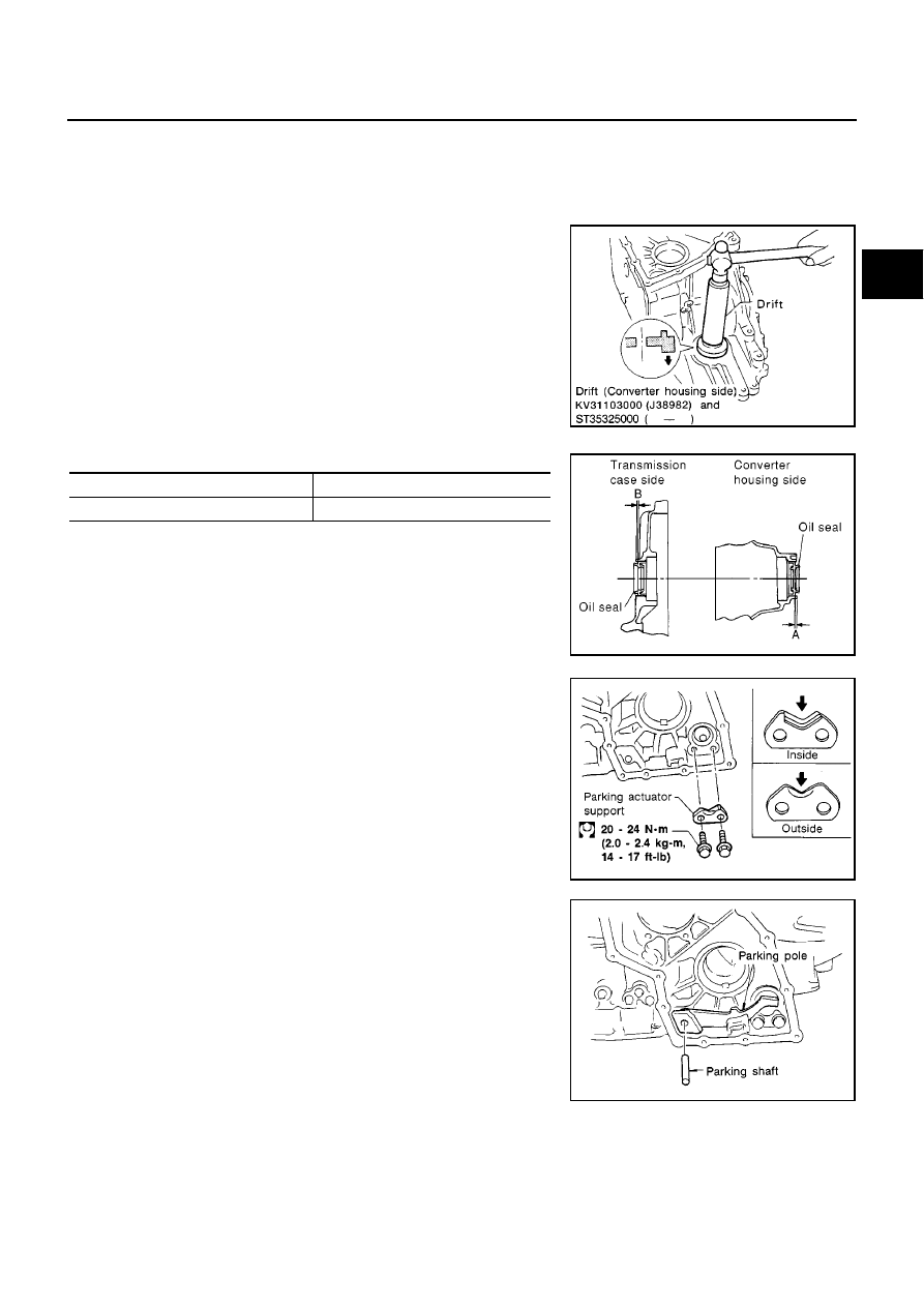
2.

Install differential side oil seals on transmission case and con-
verter housing, so that “A” and “B” are with in specification.

Unit: mm (in)

3.

Install parking actuator support to transmission case.

Pay attention to direction of parking actuator support.

4.

Install parking pawl on transmission case and fix it with parking
shaft.

AAT695

A

B

5.5 - 6.5 (0.217 - 0.256)

0.5 to 0.5 (

0.020 to 0.020)

MCIB9018E

SAT328D

SAT329D

AT-498

[ALL]

ASSEMBLY

5.

Install return spring.

Adjustment (1)

ECS009CV

DIFFERENTIAL SIDE BEARING PRELOAD

1.

Install differential side bearing outer race without adjusting shim
on transmission case.

2.

Install differential side bearing outer race on converter housing.

3.

Place final drive assembly on transmission case.

4.

Install transmission case on converter housing. Tighten trans-
mission case fixing bolts A and B to the specified torque. Refer
to

AT-417, "OVERHAUL"

.

SAT330D

SAT947DA

SAT027D

ASSEMBLY

AT-499

[ALL]

D

E

F

G

H

I

J

K

L

M

A

B

AT

5.

Attach dial indicator on differential case at transmission case
side.

6.

Insert Tool into differential side gear from converter housing.

7.

Move Tool up and down and measure dial indicator deflection.

8.

Select proper thickness of differential side bearing adjusting
shim(s) using SDS table as a guide.

9.

Remove converter housing from transmission case.

10. Remove final drive assembly from transmission case.

11. Remove differential side bearing outer race from transmission

case.

12. Reinstall differential side bearing outer race and shim(s)

selected from SDS table on transmission case.

13. Reinstall converter housing on transmission case and tighten

transmission case fixing bolts to the specified torque. Refer to

AT-417, "OVERHAUL"

.

14. Insert Tool into differential case and measure turning torque of

final drive assembly.

Turn final drive assembly in both directions several times
to seat bearing rollers correctly.

When old bearing is used again, turning torque will be
slightly less than the above.

Make sure torque is close to the specified range.

REDUCTION PINION GEAR BEARING PRELOAD

Be sure to remove final drive assembly before doing this proce-
dure.

Using caliper and straightedge, calculate a dimension “T”
(adjuster shim thickness) in the right figure by the following for-
mula and adjust the inspection standard for pre load (rotating
slide torque) as shown below.

Differential side bearing preload “T”:

0.04 - 0.09 mm (0.0016 - 0.0035 in)

Differential side bearing adjusting shim:

Refer to

AT-519, "SERVICE DATA AND SPECIFICA-

TIONS (SDS)"

.

AAT947

AAT477

Turning torque of final drive assembly (New bearing):

0.49 - 1.08 N-m (5.0 - 11.0 kg-cm, 4.3 - 9.5 in-lb)

AAT466

T = A

E

Inspection standard for preload:

0.1 - 0.69 N-m (1.1 - 7.0 kg-cm, 0.95 - 6.08 in-lb)

SAT876J

AT-500

[ALL]

ASSEMBLY

1.

Remove transmission case and final drive assembly from converter housing.

2.

Select proper thickness of reduction pinion gear bearing adjusting shim using the following procedures.

a.

Place reduction pinion gear on transmission case as shown.

b.

Place idler gear bearing on transmission case.

c.

Measure dimensions “B” “C” and “D” and calculate dimension
“A”.

Measure dimension “B” between the end of reduction pinion
gear and the surface of transmission case.

Measure dimension “B” in at least two places.

Measure dimension “C” between the surface of idler gear
bearing inner race and the surface of transmission case.

Measure dimension “C” in at least two places.

Measure dimension “D” between the end of reduction pinion
gear and the adjusting shim mating surface of reduction pin-
ion gear.

Measure dimension “D” in at least two places.

Calculate dimension “A”.

A = D

(B + C)

“A”:

Distance between the surface of idler gear bear-
ing inner race and the adjusting shim mating
surface of reduction pinion gear.

SAT333DA

SAT334DA

SAT335D

A = D

(B + C)

SAT336DA

ASSEMBLY

AT-501

[ALL]

D

E

F

G

H

I

J

K

L

M

A

B

AT

d.

Measure dimension “E” between the end of idler gear and the
idler gear bearing inner race mating surface of idler gear.

Measure dimension “E” in at least two places.

e.

Select proper thickness of reduction pinion gear bearing adjust-
ing shim.

3.

Install reduction gear and reduction pinion gear bearing adjust-
ing shim selected in step 2-e on transmission case.

4.

Press idler gear bearing inner race on idler gear.

5.

Press idler gear on reduction gear.

Press idler gear so-that idler gear can be locked by park-
ing pawl.

6.

Tighten idler gear lock nut to the specified torque.

Lock idler gear with parking pawl when tightening lock
nut.

7.

Measure turning torque of reduction pinion gear.

When measuring turning torque, turn reduction pinion
gear in both directions several times to seat bearing roll-
ers correctly.

Proper shim thickness = A

E

0.05 mm (0.0020 in)*

(*... Bearing preload)

Reduction pinion gear bearing adjusting shim:

Refer to

AT-519, "SERVICE DATA AND SPECIFICA-

TIONS (SDS)"

.

SAT337D

AAT696

SAT339D

Turning torque of reduction pinion gear:

0.1 - 0.69 N-m (1.1 - 7.0 kg-cm, 0.95 - 6.08 in-lb)

SAT340DC

AT-502

[ALL]

ASSEMBLY

OUTPUT SHAFT END PLAY

Measure clearance between side cover and the end of the out-
put shaft bearing.

Select proper thickness of adjusting shim so that clearance is
within specifications.

1.

Install bearing retainer for output shaft.

2.

Install output shaft thrust needle bearing on bearing retainer.

3.

Install output shaft on transmission case.

SAT341D

SAT347D

SAT438D

SAT439D

ASSEMBLY

AT-503

[ALL]

D

E

F

G

H

I

J

K

L

M

A

B

AT

4.

Measure dimensions “

1

” and “

2

” at side cover and then cal-

culate dimension “A”.

Measure dimension “

1

” and

2

in at least two

places.

5.

Measure dimensions “

2

” and “

3

” and then calculate dimen-

sion “B”.

Measure “

2

” and “

3

” in at least two places.

6.

Select proper thickness of adjusting shim so that output shaft
end play (clearance between side cover and output shaft bear-
ing) is within specifications.

7.

Install adjusting shim on output shaft bearing.

8.

Apply locking sealant to transmission case as shown in illustra-
tion.

9.

Install side cover on transmission case.

Apply locking sealant to the mating surface of transmis-
sion case.

“A”:

Distance between transmission case fitting
surface and adjusting shim mating surface.

A =

1

2

2

:

Height of gauge

SAT874DA

“B”:

Distance between the end of output shaft bear-
ing outer race and the side cover fitting sur-
face of transmission case.

B =

2

3

2

:

Height of gauge

SAT875DA

Output shaft end play (A

B):

0 - 0.5 mm (0 - 0.020 in)

Output shaft end play adjusting shims:

Refer to

AT-519, "SERVICE DATA AND SPECIFICA-

TIONS (SDS)"

.

SAT440D

SAT441D

SAT442D

AT-504

[ALL]

ASSEMBLY

10. Tighten side cover fixing bolts to specified torque.

Do not mix bolts A and B.

Always replace bolts A as they are self-sealing bolts.

Assembly (2)

ECS009CW

1.

Remove paper rolled around bearing retainer.

2.

Install thrust washer on bearing retainer.

Apply petroleum jelly to thrust washer.

3.

Install forward clutch assembly.

Align teeth of low & reverse brake drive plates before
installing.

Make sure that bearing retainer seal rings are not spread.

4.

Install thrust needle bearing on bearing retainer.

Apply petroleum jelly to thrust bearing.

Pay attention to direction of thrust needle bearing.

SAT124E

SAT354D

SAT355D

SAT356D

ASSEMBLY

AT-505

[ALL]

D

E

F

G

H

I

J

K

L

M

A

B

AT

5.

Install thrust needle bearing on rear internal gear.

Apply petroleum jelly to thrust needle bearing.

Pay attention to direction of thrust needle bearing.

6.

Hold forward clutch hub and turn overrun clutch hub.
Check overrun clutch hub for directions of lock and unlock.

If not as shown in illustration, check installed direction of for-
ward one-way clutch.

7.

Install rear internal gear assembly.

Align teeth of forward clutch and overrun clutch drive
plate.

8.

Install needle bearing on rear planetary carrier.

Apply petroleum jelly to needle bearing.

Pay attention to direction of needle bearing.

9.

Install rear sun gear on rear planetary carrier.

Pay attention to direction of rear sun gear.

SAT357D

SAT358D

SAT359D

SAT360D

SAT052D

AT-506

[ALL]

ASSEMBLY

10. Install rear planetary carrier on transmission case.

11. Install thrust needle bearing on front planetary carrier.

Apply petroleum jelly to thrust needle bearing.

Pay attention to direction of thrust needle bearing.

12. Install low one-way clutch to front planetary carrier by turning it

in the direction of the arrow as shown.

13. While holding front planetary carrier, turn low one-way clutch.

Check low one-way clutch for correct directions of lock and
unlock.

14. Install front planetary carrier assembly on transmission case.

15. Install snap ring with screwdriver.

Forward clutch and bearings must be correctly installed
for snap ring to fit groove of transmission case.

SAT362D

SAT363D

SAT048D

SAT047D

SAT046D

ASSEMBLY

AT-507

[ALL]

D

E

F

G

H

I

J

K

L

M

A

B

AT

16. Install needle bearing on front sun gear.

Apply petroleum jelly to needle bearing.

Pay attention to direction of needle bearing.

17. Install front sun gear on front planetary carrier.

18. Install needle bearing on front sun gear.

Apply petroleum jelly to needle bearing.

Pay attention to direction of needle bearing.

19. Install high clutch hub on front sun gear.

20. Install needle bearing on high clutch hub.

Apply petroleum jelly to needle bearing.

Pay attention to direction of needle bearing.

SAT367D

SAT368D

SAT369D

SAT370D

SAT371D

AT-508

[ALL]

ASSEMBLY

21. Remove paper rolled around input shaft.

22. Install reverse clutch assembly.

Align teeth of high clutch drive plates before installing.

23. Install reverse clutch assembly.

Align teeth of high clutch drive plates before installing.

Adjustment (2)

ECS009CX

When any parts listed below are replaced, adjust total end play and reverse clutch end play.

TOTAL END PLAY

Measure clearance between reverse clutch drum and needle
bearing for oil pump cover.

Select proper thickness of bearing race so that end play is within
specifications.

SAT372D

SAT373D

Part name

Total end play

Reverse clutch end

play

Transmission case

Overrun clutch hub

Rear internal gear

Rear planetary carrier

Rear sun gear

Front planetary carrier

Front sun gear

High clutch hub

High clutch drum

Oil pump cover

Reverse clutch drum

SAT374D

ASSEMBLY

AT-509

[ALL]

D

E

F

G

H

I

J

K

L

M

A

B

AT

1.

Measure dimensions “K” and “L” and then calculate dimension
“J”.

a.

Measure dimension “K”.

b.

Measure dimension “L”.

c.

Calculate dimension “J”.

2.

Measure dimension “M”.

a.

Place bearing race and needle bearing on oil pump assembly.

b.

Measure dimension “M”.

SAT375D

SAT376D

“J”: Distance between oil pump fitting surface of
transmission case and needle bearing mating surface
of high clutch drum.

J = K – L

SAT377D

SAT378D

“M”: Distance between transmission case fitting surface
of oil pump cover and needle bearing on oil pump cover.

“M

1

”: Indication of gauge.

SAT379D

AT-510

[ALL]

ASSEMBLY

c.

Measure thickness of straightedge “t”.

3.

Adjust total end play “T

3

”.

Select proper thickness of bearing race so that total end play is within specifications.

REVERSE CLUTCH END PLAY

Measure clearance between oil pump cover and thrust washer
for reverse clutch drum.

Select proper thickness of thrust washer so that end play is
within specification.

1.

Measure dimensions “O” and “P” and then calculate dimension
“N”.

a.

Place thrust washer on reverse clutch drum.

b.

Measure dimension “O”.

M = M

1

– t

SAT443D

T

3

= J – M

Total end play “T

3

”:

0.25 - 0.55 mm (0.0098 - 0.0217 in)

Bearing races:

Refer to

AT-519, "SERVICE DATA AND SPECIFICATIONS (SDS)"

.

SAT380D

SAT381D

SAT382D

ASSEMBLY

AT-511

[ALL]

D

E

F

G

H

I

J

K

L

M

A

B

AT

c.

Measure dimension “P”.

d.

Calculate dimension “N”.

2.

Measure dimensions “R” and “S” and then calculate dimension
“Q”.

a.

Measure dimension “R”.

b.

Measure dimension “S”.

c.

Calculate dimension “Q”.

3.

Adjust reverse clutch end play “T

4

”.

Select proper thickness of thrust washer so that reverse clutch end play is within specifications.

“N”: Distance between oil pump fitting surface of trans-
mission case and thrust washer on reverse clutch
drum.

N = O – P

SAT383D

SAT384D

SAT385D

“Q”: Distance between transmission case fitting sur-
face and thrust washer mating surface.

Q = R – S

SAT386D

T

4

= N – Q

Reverse clutch end play:

0.65 - 1.00 mm (0.0256 - 0.0394 in)

Thrust washer: Refer to

AT-519, "SERVICE DATA AND SPECIFICATIONS (SDS)"

.

AT-512

[ALL]

ASSEMBLY

Assembly (3)

ECS009CY

1.

Remove reverse clutch assembly and install needle bearing on
high clutch assembly.

Pay attention to direction of needle bearing.

2.

Install reverse clutch assembly

3.

Install anchor end pin and lock nut on transmission case.

4.

Place brake band on outside of reverse clutch drum. Tighten
anchor end pin just enough so that brake band is evenly fitted on
reverse clutch drum.

5.

Place bearing race selected in total end play adjustment step on
oil pump cover.

Apply petroleum jelly to bearing race.

6.

Place thrust washer selected in reverse clutch end play step on
reverse clutch drum.

Apply petroleum jelly to thrust washer.

SAT387D

SAT038D

SAT389D

SAT390D


Content      ..     30      31      32      33     ..