Almera Tino V10 (2003 year). Manual - part 30


  Index      Manuals     Almera Tino V10 (2003 year) - Service and Repair Manual


Search            copyright infringement  


Content      ..     28      29      30      31     ..


Almera Tino V10 (2003 year). Manual - part 30


REPAIR FOR COMPONENT PARTS

AT-465

[ALL]

D

E

F

G

H

I

J

K

L

M

A

B

AT

INSPECTION
High Clutch Snap Ring, Spring Retainer and Return Springs

Check for deformation, fatigue or damage.

If necessary, replace.

When replacing spring retainer and return springs, replace them as a set.

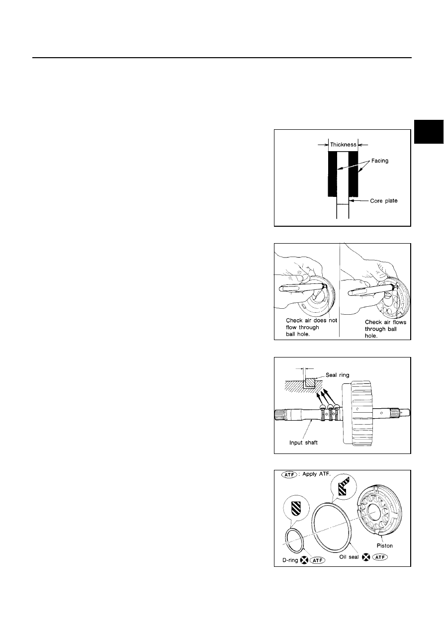
High Clutch Drive Plates

Check facing for burns, cracks or damage.

Measure thickness of facing.

If not within wear limit, replace.

High Clutch Piston

Make sure that check balls are not fixed.

Apply compressed air to check ball oil hole opposite the return
spring. Make sure there is no air leakage.

Apply compressed air to oil hole on return spring side to make
sure that air leaks past ball.

Seal Ring Clearance

Install new seal rings onto input shaft.

Measure clearance between seal ring and ring groove.

If not within allowable limit, replace input shaft assembly.

ASSEMBLY

1.

Install D-ring and oil seal on piston.

Take care with the direction of the oil seal.

Apply ATF to both parts.

Thickness of drive plate:

Standard value 2.0 mm (0.079 in)

Wear limit 1.8 mm (0.071 in)

SAT162D

SAT186D

Standard clearance: 0.08 - 0.23 mm (0.0031 - 0.0091 in)

Allowable limit: 0.23 mm (0.0091 in)

SAT187D

SAT182DA

AT-466

[ALL]

REPAIR FOR COMPONENT PARTS

2.

Install piston assembly by turning it slowly.

Apply ATF to inner surface of drum.

3.

Install return springs and spring retainer on piston.

4.

Set Tool on spring retainer and install snap ring while compress-
ing return springs.

Set Tool directly over return springs.

Do not align snap ring gap with spring retainer stopper.

5.

Install drive plates, driven plates and retaining plate.

Take care with the order and direction of plates.

6.

Install snap ring.

SAT189D

SAT191D

AAT683

SAT193D

SAT195D

REPAIR FOR COMPONENT PARTS

AT-467

[ALL]

D

E

F

G

H

I

J

K

L

M

A

B

AT

7.

Measure clearance between retaining plate and snap ring. If not
within allowable limit, select proper retaining plate.

8.

Check operation of high clutch.
Refer to

AT-463, "High Clutch"

.

9.

Install seal rings to input shaft.

Apply petroleum jelly to seal rings.

Always replace when removed.

Roll paper around seal rings to prevent seal rings from
spreading.

Specified clearance:

Standard 1.4 - 1.8 mm (0.055 - 0.071 in)

Allowable limit 2.4 mm (0.094 in)

Retaining plate:

Refer to

AT-519, "SERVICE DATA AND SPECIFICA-

TIONS (SDS)"

.

SAT199D

SAT196D

SAT197D

SAT198D

AT-468

[ALL]

REPAIR FOR COMPONENT PARTS

Forward and Overrun Clutches

ECS009CO

COMPONENTS

DISASSEMBLY

1.

Check operation of forward clutch and overrun clutch.

a.

Install bearing retainer on forward clutch drum.

b.

Apply compressed air to oil hole of forward clutch drum.

c.

Check to see that retaining plate moves to snap ring.

d.

If retaining plate does not contact snap ring:

D-ring might be damaged.

Oil seal might be damaged.

Fluid might be leaking past piston check ball.

SAT932J

SAT201D

SAT202D

REPAIR FOR COMPONENT PARTS

AT-469

[ALL]

D

E

F

G

H

I

J

K

L

M

A

B

AT

2.

Remove snap ring for forward clutch.

3.

Remove drive plates, driven plates, retaining plate and dish
plate for forward clutch.

4.

Remove snap ring for overrun clutch.

5.

Remove drive plates, driven plates, retaining plate and dish
plate for overrun clutch.

6.

Set Tool on spring retainer and remove snap ring from forward
clutch drum while compressing return springs.

Set Tool directly over return springs.

Do not expand snap ring excessively.

7.

Remove spring retainer and return springs.

Do not remove return springs from spring retainer.

8.

Remove forward clutch piston with overrun clutch piston from
forward clutch drum by turning it.

9.

Remove overrun clutch piston from forward clutch piston by
turning it.

SAT203D

SAT204D

AAT685

SAT216D

SAT215D

AT-470

[ALL]

REPAIR FOR COMPONENT PARTS

10. Remove D-rings and oil seals from forward clutch piston and

overrun clutch piston.

INSPECTION
Snap Rings, Spring Retainer

Check for deformation, fatigue or damage.

Replace if necessary.

Forward Clutch and Overrun Clutch Return

Check for deformation or damage.

Measure free length and outer diameter.

Replace if deformed or fatigued.

Forward Clutch and Overrun Clutch Drive Plates

Check facing for burns, cracks or damage.

Measure thickness of facing.

If not within wear limit, replace.

Forward Clutch and Overrun Clutch Dish Plates

Check for deformation or damage.

Measure thickness of dish plate.

If deformed or fatigued, replace.

SAT140E

Inspection standard:

Refer to

AT-519, "SERVICE DATA

AND SPECIFICATIONS (SDS)"

.

SAT138D

Thickness of drive plate:

Forward clutch

Standard value: 1.8 mm (0.071 in)

Wear limit: 1.6 mm (0.063 in)

Overrun clutch

Standard value: 1.6 mm (0.063 in)

Wear limit: 1.4 mm (0.055 in)

SAT162D

Thickness of dish plate “t”:

Forward clutch 2.5 mm (0.098 in)

Overrun clutch 2.15 mm (0.0846 in)

SAT163D

REPAIR FOR COMPONENT PARTS

AT-471

[ALL]

D

E

F

G

H

I

J

K

L

M

A

B

AT

Forward Clutch Drum

Make sure that check balls are not fixed.

Apply compressed air to check ball oil hole from outside of for-
ward clutch drum. Make sure air leaks past ball.

Apply compressed air to oil hole from inside of forward clutch
drum. Make sure there is no air leakage.

Overrun Clutch Piston

Make sure that check balls are not fixed.

Apply compressed air to check ball oil hole opposite the return
spring. Make sure there is no air leakage.

Apply compressed air to oil hole on return spring side. Make
sure that air leaks past ball.

ASSEMBLY

1.

Install D-rings and oil seals on forward clutch piston and overrun
clutch piston.

Take care with direction of oil seal.

Apply ATF to both parts.

2.

Install overrun clutch piston assembly on forward clutch piston
by turning it slowly.

Apply ATF to inner surface of forward clutch piston.

SAT213D

SAT212D

SAT208DA

SAT215D

AT-472

[ALL]

REPAIR FOR COMPONENT PARTS

3.

Install forward clutch piston assembly on forward clutch drum by
turning it slowly.

Apply ATF to inner surface of drum.

4.

Align notch in forward clutch piston with groove in forward clutch
drum.

5.

Install return spring on piston.

6.

Install spring retainer on return springs.

7.

Set Tool on spring retainer and install snap ring while compress-
ing return springs.

Set Tool directly over return springs.

Do not align snap ring gap with spring retainer stopper.

SAT216D

SAT217D

SAT218D

AAT685

SAT220D

REPAIR FOR COMPONENT PARTS

AT-473

[ALL]

D

E

F

G

H

I

J

K

L

M

A

B

AT

8.

Install drive plates, driven plates, retaining plate and dish plate
for overrun clutch.

Take care with order of plates.

9.

Install snap ring for overrun clutch.

10. Measure clearance between overrun clutch retaining plate and

snap ring.
If not within allowable limit, select proper retaining plate.

11. Install drive plates, driven plates, retaining plate and dish plate

for forward clutch.

Take care with order and direction of plates.

12. Install snap ring for forward clutch.

13. Measure clearance between forward clutch retaining plate and

snap ring.
If not within allowable limit, select proper retaining plate.

14. Check operation of forward clutch.

Refer to

AT-468, "Forward and Overrun Clutches"

.

SAT204D

Specified clearance:

Standard 1.0 - 1.4 mm (0.039 - 0.055 in)

Allowable limit 2.0 mm (0.079 in)

Overrun clutch retaining plate:

Refer to

AT-519, "SERVICE DATA AND SPECIFICA-

TIONS (SDS)"

.

SAT227D

SAT203D

Specified clearance:

Standard 0.45 - 0.85 mm (0.0177 - 0.0335 in)

Allowable limit 1.85 mm (0.0728 in)

Forward clutch retaining plate:

Refer to

AT-519, "SERVICE DATA AND SPECIFICA-

TIONS (SDS)"

.

SAT228D

SAT201D

AT-474

[ALL]

REPAIR FOR COMPONENT PARTS

15. Check operation of overrun clutch.

Refer to

AT-468, "Forward and Overrun Clutches"

.

Low & Reverse Brake

ECS009CP

COMPONENTS

DISASSEMBLY

1.

Check operation of low & reverse brake.

a.

Apply compressed air to oil hole of transmission case.

b.

Check to see that retaining plate moves to snap ring.

c.

If retaining plate does not contact snap ring:

D-ring might be damaged.

Oil seal might be damaged.

Fluid might be leaking past piston check ball.

2.

Stand transmission case.

3.

Remove snap ring.

4.

Remove drive plates, driven plates, retaining plate from trans-
mission case.

SAT202D

SAT486JA

SAT230D

SAT231D

REPAIR FOR COMPONENT PARTS

AT-475

[ALL]

D

E

F

G

H

I

J

K

L

M

A

B

AT

5.

Set Tool on spring retainer and remove snap ring while com-
pressing return springs.

Set Tool directly above return springs.

Do not expand snap ring excessively.

6.

Remove spring retainer and return springs.

Do not remove return springs from spring retainer.

7.

Apply compressed air to oil hole of transmission case while
holding piston.

8.

Remove piston from transmission case by turning it.

9.

Remove D-ring and oil seal from piston.

AAT687

SAT303E

SAT234D

SAT767G

AT-476

[ALL]

REPAIR FOR COMPONENT PARTS

INSPECTION
Low & Reverse Brake Snap Ring, Spring Retainer and Return Springs

Check for deformation, fatigue or damage.

If necessary, replace.

When replacing spring retainer and return springs, replace them as a set.

Low & Reverse Brake Drive Plate

Check facing for burns, cracks or damage.

Measure thickness of facing.

If not within wear limit, replace.

ASSEMBLY

1.

Install D-ring and oil seal on piston.

Take care with the direction of the oil seal.

Apply ATF to both parts.

2.

Stand transmission case.

3.

Install piston assembly on transmission case while turning it
slowly.

Apply ATF to inner surface of transmission case.

4.

Install return springs and spring retainer on piston.

Thickness of drive plate:

Standard value 2.0 mm (0.079 in)

Wear limit 1.8 mm (0.071 in)

SAT162D

SAT235DA

SAT239D

SAT241D

REPAIR FOR COMPONENT PARTS

AT-477

[ALL]

D

E

F

G

H

I

J

K

L

M

A

B

AT

5.

Install snap ring while compressing return springs.

Set Tool directly above return springs.

6.

Install drive plates, driven plates, retaining plates and dished
plates.

Do not align the projections on the two dished plates.

Make sure to put the plates in the correct order and direc-
tion.

7.

Install snap ring.

8.

Measure clearance between retaining plate and snap ring. If not
within allowable limit, select proper retaining plate (front side).

9.

Check operation of low & reverse brake. Refer to

AT-474, "DIS-

ASSEMBLY"

.

AAT687

SAT254E

SAT231D

Specified clearance:

Standard 1.4 - 1.8 mm (0.055 - 0.071 in)

Allowable limit 2.8 mm (0.110 in)

Retaining plate:

Refer to

AT-519, "SERVICE DATA AND SPECIFICA-

TIONS (SDS)"

.

SAT246D

SAT230D

AT-478

[ALL]

REPAIR FOR COMPONENT PARTS

Rear Internal Gear, Forward Clutch Hub and Overrun Clutch Hub

ECS009CQ

COMPONENTS

DISASSEMBLY

1.

Remove snap ring from overrun clutch hub.

2.

Remove overrun clutch hub from forward clutch hub.

3.

Remove thrust washer from forward clutch hub.

4.

Remove forward clutch hub from rear internal gear.

SAT875J

SAT249D

SAT250D

SAT251D

REPAIR FOR COMPONENT PARTS

AT-479

[ALL]

D

E

F

G

H

I

J

K

L

M

A

B

AT

5.

Remove end bearing from rear internal gear.

6.

Remove thrust washer from rear internal gear.

7.

Remove end bearing from forward one-way clutch.

8.

Remove forward one-way clutch from forward clutch hub.

SAT252D

SAT253D

SAT254D

SAT255D

AT-480

[ALL]

REPAIR FOR COMPONENT PARTS

INSPECTION
Rear Internal Gear, Forward Clutch Hub and Overrun Clutch Hub

Check rubbing surfaces for wear or damage.

Snap Ring, End Bearings and Forward One-way Clutch

Check snap ring and end bearings for deformation and damage.

Check forward one-way clutch for wear and damage.

ASSEMBLY

1.

Install forward one-way clutch on forward clutch.

Take care with the direction of forward one-way clutch.

2.

Install end bearing on forward one-way clutch.

Apply petroleum jelly to bearing.

SAT256D

SAT257D

SAT976H

MCIB9019E


Content      ..     28      29      30      31     ..