Almera Tino V10 (2003 year). Manual - part 26


  Index      Manuals     Almera Tino V10 (2003 year) - Service and Repair Manual


Search            copyright infringement  


Content      ..     24      25      26      27     ..


Almera Tino V10 (2003 year). Manual - part 26


CAN COMMUNICATION LINE

AT-401

[ALL]

D

E

F

G

H

I

J

K

L

M

A

B

AT

Diagnostic Procedure

ECS009BY

1.

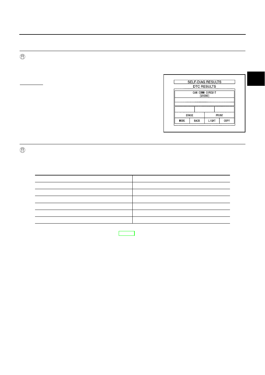
CHECK CAN COMMUNICATION CIRCUIT

With CONSULT-II

1.

Turn ignition switch to “ON” position. (Do not start engine.)

2.

Select “DATA MONITOR” mode for “A/T” with CONSULT-II.

3.

The “CON COMM CIRCUIT” is detected.

Yes or No?

Yes

>> Print out CONSULT-II screen, GO TO 2.

NG

>> INSPECTION END

2.

CHECK CAN COMMUNICATION SIGNALS

With CONSULT-II

1.

Turn ignition switch to “ON” position. (Do not start engine.)

2.

Select “CAN COMM SIGNALS” in “DATA MONITOR” mode for “A/T” with CONSULT-II.

CAN Communication Signals

>> Print out CONSULT-II screen, go to EL-459, “CAN Communication”.

PCIA0061E

Normal conditions

Abnormal conditions (examples)

CAN COMM: OK

CAN COMM: OK

CAN CIRC 1: OK

CAN CIRC 1: UNKWN

CAN CIRC 2: OK

CAN CIRC 2: UNKWN

CAN CIRC 3: UNKWN

CAN CIRC 3: UNKWN

CAN CIRC 4: OK

CAN CIRC 4: UNKWN

CAN CIRC 5: UNKWN

CAN CIRC 5: UNKWN

AT-402

[ALL]

A/T SHIFT LOCK SYSTEM

A/T SHIFT LOCK SYSTEM

PFP:34950

Description

ECS009BZ

The mechanical key interlock mechanism also operates as a shift lock:
With the key switch turned to ON, the selector lever cannot be shifted from “P” (parking) to any other posi-
tion unless the brake pedal is depressed.
With the key removed, the selector lever cannot be shifted from “P” to any other position.
The key cannot be removed unless the selector lever is placed in “P”.

The shift lock and key interlock mechanisms are controlled by the ON-OFF operation of the shift lock sole-
noid and by the operation of the rotator and slider located inside the key cylinder.

Shift Lock System Electrical Parts Location

ECS009C0

MCIA0108E

A/T SHIFT LOCK SYSTEM

AT-403

[ALL]

D

E

F

G

H

I

J

K

L

M

A

B

AT

Wiring Diagram — SHIFT —

ECS009C1

YAT389A

AT-404

[ALL]

A/T SHIFT LOCK SYSTEM

Diagnostic Procedure

ECS009C2

SYMPTOM 1:

Selector lever cannot be moved from “P” position with key in ON position and brake pedal
applied.

Selector lever can be moved from “P” position with key in ON position and brake pedal released.

Selector lever can be moved from “P” position when key is removed from key cylinder.

SYMPTOM 2:
Ignition key cannot be removed when selector lever is set to “P” position. It can be removed when
selector lever is set to any position except “P”.

1.

CHECK KEY INTERLOCK CABLE

Check key interlock cable for damage.

OK or NG

OK

>> GO TO 2

NG

>> Repair key interlock cable. Refer to

AT-408, "KEY INTERLOCK CABLE"

.

2.

CHECK SELECTOR LEVER POSITION

Check selector lever position for damage.

OK or NG

OK

>> GO TO 3

NG

>> Check selector lever. Refer to

AT-412, "Park/Neutral Position (PNP) Switch Adjustment"

.

3.

CHECK POWER SOURCE

1.

Turn ignition switch to “ON” position.
(Do not start engine.)

2.

Check voltage between stop lamp switch harness terminal 1 and ground.

OK or NG

OK

>> GO TO 4

NG

>> Check the following items:

1. Harness for short or open between battery and stop

lamp switch harness terminal 1

2. Fuse
3. Ignition switch (Refer to EL-11, “Power Supply Rout-

ing”.)

Voltage: Battery voltage

MCIA0109E

A/T SHIFT LOCK SYSTEM

AT-405

[ALL]

D

E

F

G

H

I

J

K

L

M

A

B

AT

4.

CHECK INPUT SIGNAL (A/T DEVICE)

Turn ignition switch to “ON” position.
(Do not start engine.)

Check voltage between A/T device harness terminal 7 and ground.

OK or NG

OK

>> GO TO 5

NG

>> Check the following items:

1. Harness for short and open between battery and stop

lamp switch harness connector 1.

2. Harness for short or open between stop lamp switch harness connector 2 and A/T device har-

ness connector 7.

3. Fuse
4. Stop lamp switch (Refer to

AT-407, "A/T DEVICE CHECK"

.)

5.

CHECK GROUND CIRCUIT

1.

Turn ignition switch to “OFF” position.

2.

Disconnect A/T device harness connector.

3.

Check continuity between A/T device harness terminal 6 and ground.

If OK, check harness for short to ground and short to power.

OK or NG

OK

>> GO TO 6

NG

>> Repair open circuit or short to ground or short to power

in harness or connectors.

Voltage:

Brake pedal depressed:

Battery voltage

Brake pedal released:

0V

MCIA0110E

Continuity should exist.

MCIA0111E

AT-406

[ALL]

A/T SHIFT LOCK SYSTEM

6.

CHECK RELAY CIRCUIT

1.

Turn ignition switch to ON.
Check voltage between terminal 7 - 6 and 5 - 6.

OK or NG

OK

>> GO TO 7

NG

>> Replace A/T device.

7.

CHECK PARK POSITION SWITCH

Refer to

AT-407, "A/T DEVICE CHECK"

.

OK or NG

OK

>> GO TO 8

NG

>> Replace A/T device.

8.

CHECK SHIFT LOCK SOLENOID

Refer to

AT-407, "A/T DEVICE CHECK"

.

OK or NG

OK

>> GO TO 9

NG

>> Replace A/T device.

9.

SHIFT LOCK OPERATION

1.

Reconnect shift lock harness connector.

2.

Turn ignition switch from “OFF” to “ON” position. (Do not start engine.)

3.

Recheck shift lock operation.

OK or NG

OK

>> INSPECTION END

NG

>> 1. Perform A/T device input/output signal inspection test.

2. If NG, recheck harness connector connection.

MCIA0112E

A/T SHIFT LOCK SYSTEM

AT-407

[ALL]

D

E

F

G

H

I

J

K

L

M

A

B

AT

A/T DEVICE CHECK
1. Shift Lock Solenoid

Check operation sound.
When ignition switch is turned to “ON” position and selector lever is set in “P” position.

2. Park Position Switch

Check resistance between A/T device harness terminal 6 and 7.

STOP LAMP SWITCH

Check continuity between terminals 1 and 2.

Check stop lamp switch after adjusting brake pedal — refer to
BR-14, 
“Brake Pedal and Bracket”.

Brake pedal

Operation sound

Depressed

Yes

Released

No

Condition

Resistance

When selector lever is set in “P” position and selector
lever button is released

111

When selector lever is not set in “P” position and selector
lever button is released

0

MCIA0113E

Condition

Continuity

When brake pedal is depressed

Yes

When brake pedal is released

No

MCIA0114E

AT-408

[ALL]

KEY INTERLOCK CABLE

KEY INTERLOCK CABLE

PFP:34908

Components

ECS009C3

CAUTION:

Install key interlock cable in such a way that it will not be damaged by sharp bends, twists or inter-
ference with adjacent parts.

After installing key interlock cable to control device, make sure that casing cap and bracket are
firmly secured in their positions.

Removal

ECS009C4

1.

Unlock slider by squeezing lock tabs on slider from adjuster
holder and remove interlock rod from cable.

MCIA0115E

SAT246K

KEY INTERLOCK CABLE

AT-409

[ALL]

D

E

F

G

H

I

J

K

L

M

A

B

AT

2.

Remove lock plate from steering lock assembly and remove key
interlock cable.

Installation

ECS009C5

1.

Turn ignition key to lock position.

2.

Set A/T selector lever to P position.

3.

Set key interlock cable to steering lock assembly and install lock
plate.

4.

Clamp cable to steering column and fix to control cable with
band.

5.

Insert interlock rod into adjuster holder.

6.

Install casing cap to bracket.

7.

Move slider in order to fix adjuster holder to interlock rod.

SAT247K

SAT247K

SAT248K

SAT249K

AT-410

[ALL]

ON-VEHICLE SERVICE

ON-VEHICLE SERVICE

PFP:00000

Control Valve Assembly and Accumulators

ECS009C6

REMOVAL

1.

Drain ATF from transaxle.

2.

Remove oil pan and gasket.

3.

Disconnect A/T solenoid valve harness connector.

4.

Remove snap ring from A/T solenoid valve harness terminal
body.

5.

Remove A/T solenoid valve harness by pushing terminal body
into transmission case.

SAT992C

MCIB9008E

AAT265A

ON-VEHICLE SERVICE

AT-411

[ALL]

D

E

F

G

H

I

J

K

L

M

A

B

AT

6.

Remove control valve assembly by removing fixing bolts.

Bolt length, number and location:

Be careful not to drop manual valve and servo release accumulator return springs.

7.

Disassemble and inspect control valve assembly if necessary. Refer to

AT-410, "Control Valve Assembly

and Accumulators"

.

8.

Remove servo release and N-D accumulators by applying com-
pressed air if necessary.

Hold each piston with a rag.

INSTALLATION

Tighten fixing bolts to specification.

Set manual shaft in Neutral position, then align manual
plate with groove in manual valve.

After installing control valve assembly to transmission
case, make sure that selector lever can be moved to all
positions.

AAT260A

Bolt symbol

A

B

C

Bolt length “

” mm (in)

40.0 mm

(1.575 in)

33.0 mm

(1.299 in)

43.5 mm

(1.713 in)

Number of bolts

5

6

2

SAT935J

: 7 - 9 N-m (0.7 - 0.9 kg-m, 61 - 78 in-lb)

SAT497H

AT-412

[ALL]

ON-VEHICLE SERVICE

Control Cable Adjustment

ECS009C7

Move selector lever from the “P” position to the “1” position. You
should be able to feel the detentes in each position. If the detentes
cannot be felt or if the pointer indicating the position is improperly
aligned, the control cable needs adjustment.

1.

Place selector lever in “P” position.

2.

Loosen control cable lock nut and place manual shaft in “P”
position.

3.

Pull control cable, by specified force, in the direction of the arrow
shown in the illustration.

4.

Return control cable in the opposite direction of the arrow for 1.0
mm (0.039 in).

5.

Tighten control cable lock nut.

6.

Move selector lever from “P” to “1” position again. Make sure
that selector lever moves smoothly.

7.

Apply grease to contacting areas of selector lever and control
cable. Install any part removed.

Park/Neutral Position (PNP) Switch Adjustment

ECS009C8

1.

Remove control cable end from manual shaft.

2.

Set manual shaft in “N” position.

3.

Loosen PNP switch fixing bolts.

4.

Use a 4 mm (0.157 in) pin for this adjustment.

a.

Insert the pin straight into the manual shaft adjustment hole.

b.

Rotate PNP switch until the pin can also be inserted straight into
hole in PNP switch.

5.

Tighten PNP switch fixing bolts.

6.

Remove pin from adjustment hole after adjusting PNP switch.

7.

Reinstall any part removed.

8.

Adjust control cable. Refer to

AT-412, "Control Cable Adjust-

ment"

.

9.

Check continuity of PNP switch. Refer to

AT-113, "DTC P0705

PARK/NEUTRAL POSITION (PNP) SWITCH"

.

Specified force: 6.9 N (0.7 kg, 1.5 lb)

AAT980

SAT479J

SAT480J

ON-VEHICLE SERVICE

AT-413

[ALL]

D

E

F

G

H

I

J

K

L

M

A

B

AT

Differential Side Oil Seal Replacement

ECS009C9

1.

Remove drive shaft assemblies. Refer to AX-10, “Drive Shaft”.

2.

Remove oil seals.

3.

Install oil seals.

Apply ATF to oil seal surface before installing.

Drift for installing

Install oil seals so that dimensions “A” and “B” are within
specifications.

Unit: mm (in)

4.

Reinstall any part removed.

Revolution Sensor Replacement

ECS009CA

1.

Disconnect revolution sensor harness connector.

2.

Remove harness bracket from A/T.

3.

Remove revolution sensor from A/T.

4.

Reinstall any part removed.

Always use new sealing parts.

SAT905D

AAT976

A

B

5.5 to 6.5 (0.217 to 0.256)

0.5 to 0.5 (

0.020 to 0.020)

MCIB9018E

SAT303G

AT-414

[ALL]

REMOVAL AND INSTALLATION

REMOVAL AND INSTALLATION

PFP:00000

Removal

ECS009CB

CAUTION:

Before separating transaxle from engine, remove the crankshaft
position sensor (OBD) from transaxle. Be careful not to damage
sensor.

1.

Remove battery and bracket.

2.

Remove air duct between throttle body and air cleaner.

3.

Disconnect A/T solenoid harness connector, PNP switch har-
ness connector and revolution sensor harness connector.

4.

Remove crankshaft position sensor (OBD) from transaxle.

5.

Drain ATF from transaxle.

6.

Disconnect control cable from transaxle.

7.

Disconnect fluid cooler hoses.

8.

Remove drive shafts. Refer to AX-10, “Drive Shaft”.

9.

Remove the intake manifold support bracket.

10. Remove starter motor from transaxle.

11. Remove upper bolts fixing transaxle to engine.
12. Support transaxle with a jack.

13. Remove center member.

14. Remove center member, engine insulator and engine mounting bracket.

SAT501HA

Tighten bolts to specified torque.

: 41 - 52 N-m (4.2 - 5.3 kg-m, 30 - 38 ft-lb)

SAT304G

AAT469

REMOVAL AND INSTALLATION

AT-415

[ALL]

D

E

F

G

H

I

J

K

L

M

A

B

AT

15. Remove dust cover from converter housing.

Rotate crankshaft to gain access to securing bolts.

16. Remove securing bolts between drive plate and torque con-

verter. when crank shaft rotates, turn to right at the front side of
engine.

17. Support engine with a jack.

18. Remove bolts fixing transaxle to engine.

19. Lower transaxle while supporting it with a jack.

Installation

ECS009CC

1.

Check drive plate runout.

CAUTION:

Do not allow any magnetic materials to contact the ring
gear teeth.

If this runout is out of allowance, replace drive plate with ring
gear.

2.

When connecting torque converter to transaxle, measure dis-
tance “A” to be certain that they are correctly assembled.

3.

Install torque converter to drive plate.

With converter installed, rotate crankshaft several turns
to check that transaxle rotates freely without binding.

AAT259A

Maximum allowable runout

:

Refer to

EM-95, "FLYWHEEL RUNOUT"

.

SAT977H

Distance “A”: 21.1 mm (0.831 in) or more

SAT573D

AAT266A

AT-416

[ALL]

REMOVAL AND INSTALLATION

4.

Tighten bolts fixing transaxle.

5.

Reinstall any part removed.

6.

Adjust control cable. Refer to

AT-412, "Control Cable Adjust-

ment"

.

7.

Check continuity of PNP switch. Refer to

AT-113, "DTC P0705

PARK/NEUTRAL POSITION (PNP) SWITCH"

.

8.

Refill transaxle with ATF and check fluid level.

9.

Move selector lever through all positions to be sure that tran-
saxle operates correctly. With parking brake applied, idle
engine. Move selector lever through “N” to “D”, to “2”, to “1” and
“R” positions. A slight shock should be felt through the hand
gripping the selector each time the transaxle is shifted.

10. Perform road test. Refer to

AT-268, "Road Test"

.

Bolt No.

Tightening torque

N-m (kg-m, ft-lb)

Bolt length “ L ”

mm (in)

1

70 - 79 (7.1 - 8.1, 51 - 59)

55 (2.17)

2

70 - 79 (7.1 - 8.1, 51 - 59)

50 (1.97)

3

70 - 79 (7.1 - 8.1, 51 - 59)

65 (2.56)

4

16 - 21 (1.6 - 2.1, 12 - 15)

35 (1.38)

5

16 - 21 (1.6 - 2.1, 12 - 15)

47 (1.85)

MCIB9009E

SAT638A


Content      ..     24      25      26      27     ..