Almera Tino V10 (2003 year). Manual - part 25


  Index      Manuals     Almera Tino V10 (2003 year) - Service and Repair Manual


Search            copyright infringement  


Content      ..     23      24      25      26     ..


Almera Tino V10 (2003 year). Manual - part 25


BATT/FLUID TEMP SEN (A/T FLUID TEMP SENSOR CIRCUIT AND TCM POW-

ER SOURCE)

AT-385

[ALL]

D

E

F

G

H

I

J

K

L

M

A

B

AT

3.

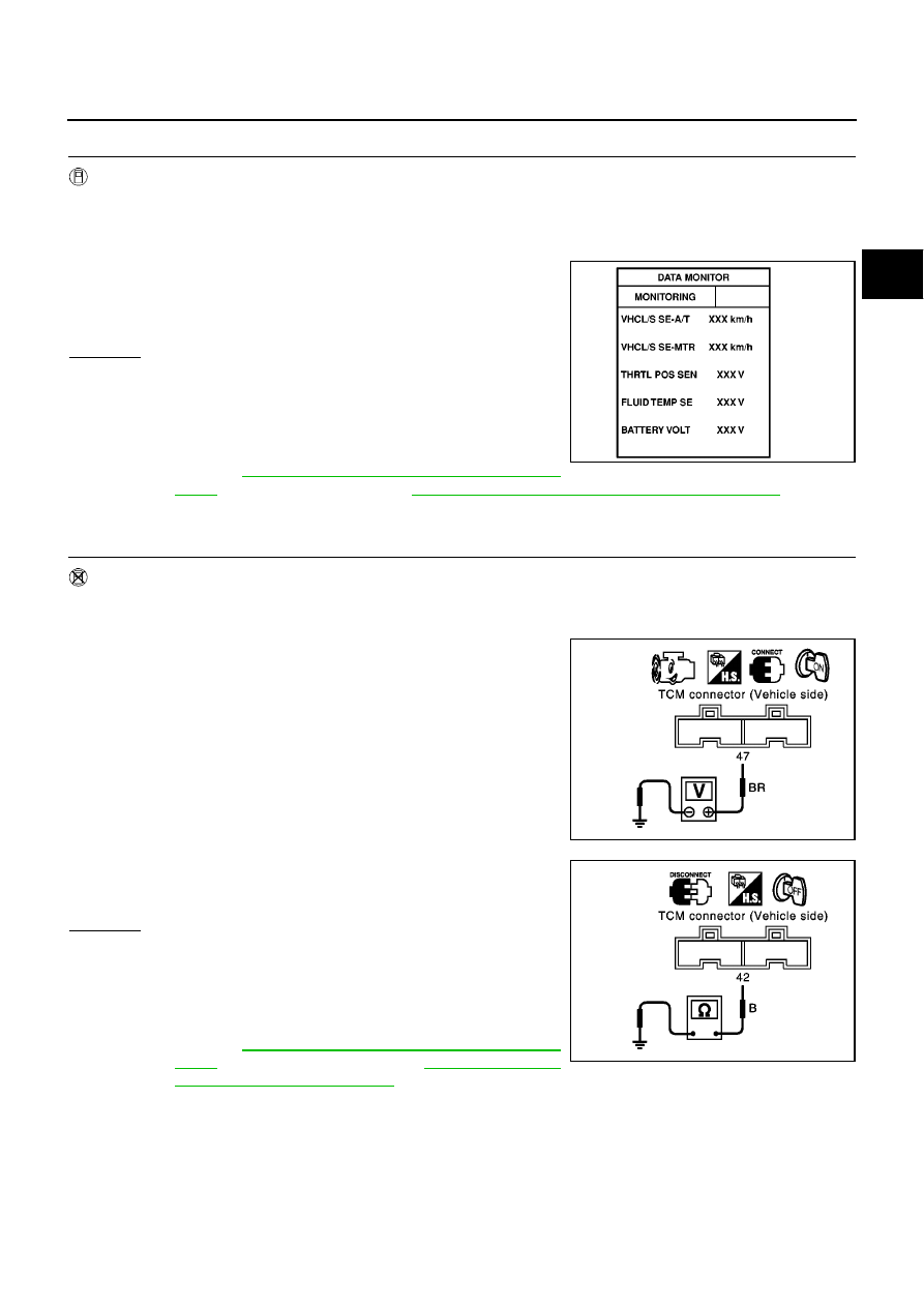
CHECK INPUT SIGNAL OF A/T FLUID TEMPERATURE SENSOR (WITH CONSULT-II)

With CONSULT-II

1.

Start engine.

2.

Select “TCM INPUT SIGNALS” in “DATA MONITOR” mode for “A/T” with CONSULT-II.

3.

Read out the value of “FLUID TEMP SE”.

OK or NG

OK

>> GO TO 5

NG

>> Check the following item:

Harness for short or open between TCM, ECM and
terminal cord assembly (Main harness)

Ground circuit for ECM
Refer to

EC-139, "POWER SUPPLY CIRCUIT FOR

ECM"

(With EURO-OBD) and

EC-645, "POWER SUPPLY CIRCUIT FOR ECM"

(Without

EURO-OBD).

4.

CHECK INPUT SIGNAL OF A/T FLUID TEMPERATURE SENSOR (WITHOUT CONSULT-II)

Without CONSULT-II

1.

Start engine.

2.

Check voltage between TCM terminal 47 and ground while warming up A/T.

3.

Turn ignition switch to “OFF” position.

4.

Disconnect TCM harness connector.

5.

Check resistance between terminal 42 and ground.

OK or NG

OK

>> GO TO 5

NG

>> Check the following item:

Harness for short or open between TCM, ECM and
terminal cord assembly (Main harness)

Ground circuit for ECM
Refer to

EC-139, "POWER SUPPLY CIRCUIT FOR

ECM"

(With EURO-OBD) and

EC-645, "POWER

SUPPLY CIRCUIT FOR ECM"

(Without EURO-OBD).

Voltage

Cold [20

°

C (68

°

F)]

Hot [80

°

C (176

°

F)]:

Approximately 1.5V

0.5V

SAT614J

Voltage

Cold [20

°

C (68

°

F)]

Hot [80

°

C (176

°

F)]:

Approximately 1.5V

0.5V

SCIA0738E

Continuity should exist.

SCIA0739E

AT-386

[ALL]

BATT/FLUID TEMP SEN (A/T FLUID TEMP SENSOR CIRCUIT AND TCM POW-

ER SOURCE)

5.

CHECK DTC

Perform

AT-382, "SELF-DIAGNOSIS CODE CONFIRMATION PROCEDURE"

.

OK or NG

OK

>> INSPECTION END

NG

>> 1. Perform TCM input/output signal inspection.

2. If NG, recheck TCM pin terminals for damage or loose connection with harness connector.

Component Inspection

ECS009BM

A/T FLUID TEMPERATURE SENSOR

For removal, refer to

AT-410, "Control Valve Assembly and Accumulators"

.

Check resistance between two terminals while changing temper-
ature as shown at left.

Temperature

°

C (

°

F)

Resistance

20 (68)

Approximately 2.5 k

80 (176)

Approximately 0.3 k

SAT298F

ENGINE SPEED SIGNAL

AT-387

[ALL]

D

E

F

G

H

I

J

K

L

M

A

B

AT

ENGINE SPEED SIGNAL

PFP:24825

Description

ECS009BN

The engine speed signal is sent from the ECM to the TCM.

TCM TERMINALS AND REFERENCE VALUE

Remarks: Specification data are reference values.

ON BOARD DIAGNOSIS LOGIC

SELF-DIAGNOSIS CODE CONFIRMATION PROCEDURE

After the repair, perform the following procedure to confirm the malfunction is eliminated.

With CONSULT-II

1.

Start engine.

2.

Select “SELF-DIAG RESULTS” mode for A/T with CONSULT-II.

3.

Drive vehicle under the following conditions:
Selector lever in “D” position, vehicle speed higher than 10 km/h
(6 MPH), throttle opening greater than 1/8 of the full throttle
position and driving for more than 10 seconds.

4.

If DTC is detected, go to

AT-390, "Diagnostic Procedure"

.

Termi-

nal No.

Wire color

Item

Condition

Judgement stan-

dard

(Approx.)

39

L/OR

Engine speed
signal

and

Refer to

EC-102, "ECM INSPECTION TABLE"

(EURO-OBD),

EC-610, "ECM INSPECTION

TABLE"

(EXCEPT FOR EURO-OBD).

Diagnostic trouble code

Malfunction is detected when...

Check item (Possible cause)

: ENGINE SPEED SIG

TCM does not receive the proper voltage
signal from ECM.

Harness or connectors
(The sensor circuit is open or shorted.)

: 9th judgement flicker

SAT014K

SAT020K

AT-388

[ALL]

ENGINE SPEED SIGNAL

Without CONSULT-II

1.

Start engine.

2.

Drive vehicle under the following conditions:
Selector lever in “D” position, vehicle speed higher than 10 km/h
(6 MPH), throttle opening greater than 1/8 of the full throttle
position and driving for more than 10 seconds.

3.

Perform self-diagnosis.
Refer to

AT-252, "Diagnostic Procedure Without CONSULT-II"

.

4.

If DTC is detected, go to

AT-390, "Diagnostic Procedure"

.

MCIA0116E

ENGINE SPEED SIGNAL

AT-389

[ALL]

D

E

F

G

H

I

J

K

L

M

A

B

AT

Wiring Diagram — AT — ENGSS

ECS009BO

YAT372A

AT-390

[ALL]

ENGINE SPEED SIGNAL

Diagnostic Procedure

ECS009BP

1.

CHECK DTC WITH ECM

Perform “Overall function check” for ignition signal. Refer to

EC-518, "Diagnostic Procedure"

.

OK or NG

OK (With CONSULT-II)>>GO TO 2
OK (Without CONSULT-II)>>GO TO 3
NG

>> Follow the construction of

EC-518, "Diagnostic Procedure"

.

2.

CHECK INPUT SIGNAL (WITH CONSULT-II)

With CONSULT-II

1.

Start engine.

2.

Select “TCM INPUT SIGNALS” in “DATA MONITOR” mode for
“A/T” with CONSULT-II.

3.

Read out the value of “ENGINE SPEED”.
Check engine speed changes according to throttle position.

OK or NG

OK

>> GO TO 4

NG

>> Check the following items:

Harness for short or open between TCM and ECM

Resistor and ignition coil
Refer to

EC-514, "IGNITION SIGNAL"

.

3.

CHECK INPUT SIGNAL (WITHOUT CONSULT-II)

Without CONSULT-II

1.

Start engine.

2.

Check voltage between TCM terminal 39 and ground.

OK or NG

OK

>> GO TO 4

NG

>> Check the following items:

Harness for short or open between TCM and ECM

Resistor and ignition coil
Refer to

EC-514, "IGNITION SIGNAL"

.

SAT014K

SAT645J

Voltage (Idle speed):

Refer to

EC-514, "IGNITION SIGNAL"

.

SCIA0740E

ENGINE SPEED SIGNAL

AT-391

[ALL]

D

E

F

G

H

I

J

K

L

M

A

B

AT

4.

CHECK DTC

Perform

AT-387, "SELF-DIAGNOSIS CODE CONFIRMATION PROCEDURE"

.

OK or NG

OK

>> INSPECTION END

NG

>> 1. Perform TCM input/output signal inspection.

2. If NG, recheck TCM pin terminals for damage or loose connection with harness connector.

AT-392

[ALL]

LINE PRESSURE SOLENOID VALVE

LINE PRESSURE SOLENOID VALVE

PFP:31940

Description

ECS009BQ

The line pressure solenoid valve regulates the oil pump discharge
pressure to suit the driving condition in response to a signal sent
from the TCM.

NOTE:
The line pressure duty cycle value is not consistent when the
closed throttle position switch is “ON”. To confirm the line
pressure duty cycle at low pressure, the accelerator (throttle)
should be open until the closed throttle position switch is
“OFF”.

CONSULT-II REFERENCE VALUE IN DATA MONITOR MODE

Remarks: Specification data are reference values.

NOTE:
The line pressure duty cycle value is not consistent when the closed throttle position switch is “ON”. To confirm the line pressure duty
cycle at low pressure, the accelerator (throttle) should be open until the closed throttle position switch is “OFF”.

TCM TERMINALS AND REFERENCE VALUE

Remarks: Specification data are reference values.

ON BOARD DIAGNOSIS LOGIC

SCIA0735E

Monitor item

Condition

Specification

Line pressure solenoid valve duty

Small throttle opening

(Low line pressure)

Large throttle opening

(High line pressure)

Approximately 24%

Approximately 95%

Termi-

nal No.

Wire color

Item

Condition

Judgement stan-

dard

(Approx.)

1

R/W

Line pressure
solenoid valve

When releasing accelerator pedal
after warming up engine.

1.5 - 3.0V

When depressing accelerator pedal
fully after warming up engine.

0V

2

P/B

Line pressure
solenoid valve
(with dropping
resistor)

When releasing accelerator pedal
after warming up engine.

4 - 14V

When depressing accelerator pedal
fully after warming up engine.

0V

Diagnostic trouble code

Malfunction is detected when...

Check items (Possible cause)

: LINE PRESSURE S/V

TCM detects an improper voltage drop
when it tries to operate the solenoid valve.

Harness or connectors
(The solenoid circuit is open or shorted.)

Line pressure solenoid valve

: 10th judgement flicker

LINE PRESSURE SOLENOID VALVE

AT-393

[ALL]

D

E

F

G

H

I

J

K

L

M

A

B

AT

SELF-DIAGNOSIS CODE CONFIRMATION PROCEDURE

After the repair, perform the following procedure to confirm the malfunction is eliminated.

With CONSULT-II

1.

Start engine.

2.

Select “SELF-DIAG RESULTS” mode for A/T with CONSULT-II.

3.

With brake pedal depressed, shift the lever from “P”

“N”

“D”

“N”

“P” positions.

4.

If DTC is detected, go to

AT-395, "Diagnostic Procedure"

.

Without CONSULT-II

1.

Start engine.

2.

With brake pedal depressed, shift the lever from “P”

“N”

“D”

“N”

“P” positions.

3.

Perform self-diagnosis.
Refer to

AT-252, "Diagnostic Procedure Without CONSULT-II"

.

4.

If DTC is detected, go to

AT-395, "Diagnostic Procedure"

.

SAT014K

MCIA0117E

AT-394

[ALL]

LINE PRESSURE SOLENOID VALVE

Wiring Diagram — AT — LPSV

ECS009BR

YAT378A

LINE PRESSURE SOLENOID VALVE

AT-395

[ALL]

D

E

F

G

H

I

J

K

L

M

A

B

AT

Diagnostic Procedure

ECS009BS

1.

CHECK VALVE RESISTANCE

1.

Turn ignition switch to “OFF” position.

2.

Disconnect terminal cord assembly connector in engine compartment.

3.

Check resistance between terminal 4 and ground.

OK or NG

OK

>> GO TO 2

NG

>> 1. Remove control valve assembly. Refer to

AT-410,

"Control Valve Assembly and Accumulators"

.

2. Check the following items:

Line pressure solenoid valve
Refer to

AT-397, "Component Inspection"

.

Harness of terminal cord assembly for short or open

2.

CHECK POWER SOURCE CIRCUIT

1.

Turn ignition switch to “OFF” position.

2.

Disconnect TCM harness connector.

3.

Check resistance between terminal 4 and TCM harness connector terminal 2.

OK or NG

OK

>> GO TO 3

NG

>> Check the following items:

Dropping resistor
Refer to

AT-397, "Component Inspection"

.

Harness for short or open between TCM terminal 2
and terminal cord assembly (Main harness)

Resistance: 2.5 - 5

MCIA0085E

Resistance: 10 - 15

MCIA0086E

AT-396

[ALL]

LINE PRESSURE SOLENOID VALVE

3.

CHECK POWER SOURCE CIRCUIT

1.

Turn ignition switch to “OFF” position.

2.

Check resistance between terminal 4 and TCM harness connector terminal 1.

If NG, check harness for short to ground and short to power.

3.

Reinstall any part removed.

OK or NG

OK

>> GO TO 4

NG

>> Repair open circuit or short to ground or short to power

in harness or connectors.

4.

CHECK DTC

Perform

AT-393, "SELF-DIAGNOSIS CODE CONFIRMATION PROCEDURE"

.

OK or NG

OK

>> INSPECTION END

NG

>> 1. Perform TCM input/output signal inspection.

2. If NG, recheck TCM pin terminals for damage or loose connection with harness connector.

Resistance: Approx. 0

MCIA0087E

LINE PRESSURE SOLENOID VALVE

AT-397

[ALL]

D

E

F

G

H

I

J

K

L

M

A

B

AT

Component Inspection

ECS009BT

LINE PRESSURE SOLENOID VALVE

For removal, refer to

AT-410, "Control Valve Assembly and Accumulators"

.

Resistance Check

Check resistance between two terminals.

Operation Check

Check solenoid valve by listening for its operating sound while
applying battery voltage to the terminal and ground.

Solenoid valve

Terminal No.

Resistance

(Approx.)

Line pressure
solenoid valve

4

Ground

2.5 - 5

MCIA0088E

MCIA0089E

AT-398

[ALL]

LINE PRESSURE SOLENOID VALVE

DROPPING RESISTOR

Check resistance between two terminals.

Resistance: 10 - 15

MCIA0090E

CAN COMMUNICATION LINE

AT-399

[ALL]

D

E

F

G

H

I

J

K

L

M

A

B

AT

CAN COMMUNICATION LINE

PFP:31940

Description

ECS009BU

CAN (Controller Area Network) is a serial communication line for real time application. It is an on-vehicle mul-
tiplex communication line with high data communication speed and excellent error detection ability. Many elec-
tronic control units are equipped onto a vehicle, and each control unit shares information and links with other
control units during operation (not independent). In CAN communication, control units are connected with 2
communication lines (CAN H line, CAN L line) allowing a high rate of information transmission with less wiring.
Each control unit transmits/receives data but selectively reads required data only.

TCM TERMINALS AND REFERENCE VALUE

Remarks: Specification data are reference values.

*: This terminal is connected to the ECM.

On Board Diagnosis Logic

ECS009BV

**: A/T COMM LINE means CAN communication line.

Self-Diagnosis Code Confirmation Procedure

ECS009BW

After the repair, perform the following procedure to confirm the malfunction is eliminated.

WITH CONSULT-II

1.

Turn ignition switch “ON”.

2.

Select “DATA MONITOR” mode for “A/T” with CONSULT-II.

3.

Wait at least 6 seconds or start engine and wait for at least 6
seconds.

4.

If DTC is detected, go to

AT-401, "Diagnostic Procedure"

.

WITHOUT CONSULT-II

1.

Turn ignition switch “ON”.

2.

Wait at least 6 seconds or start engine and wait at least 6 sec-
onds.

3.

Perform self-diagnosis.
Refer to

AT-252, "Diagnostic Procedure Without CONSULT-II"

.

4.

If DTC is detected, go to

AT-401, "Diagnostic Procedure"

.

Termi-

nal No.

Wire color

Item

Condition

Judgement

standard

(Approx.)

5

L

CAN (H)

6

R

CAN (L)

Diagnostic trouble code

Malfunction is detected when...

Check items (Possible cause)

: A/T COMM LINE**

The ECM-AT communication line is open
or shorted.

Harness or connectors
(The solenoid circuit is open or shorted.)

Line pressure solenoid valve

: 11th judgement flicker

SAT014K

MCIA0118E

AT-400

[ALL]

CAN COMMUNICATION LINE

Wiring Diagram — AT — CAN

ECS009BX

YAT383A


Content      ..     23      24      25      26     ..