Nissan Almera Tino V10. Manual - part 940
SMT191A
Mainshaft and Gears
DISASSEMBLY
NLMT0014
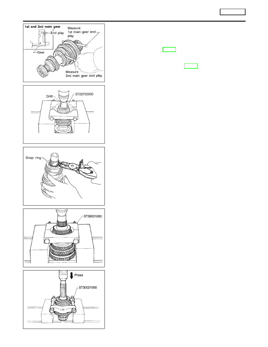
1.
Before disassembly, check 1st and 2nd main gear end plays.
Gear end play:
Refer to SDS, MT-98.
If not within specification, disassemble and check contact sur-
face of gear, shaft and hub. Check clearance of snap ring
groove. Refer to “ASSEMBLY”, MT-76.
SMT638AA
2.
Press out mainshaft rear bearing.
SMT044A
3.
Remove thrust washer and snap ring.
SMT045AA
4.
Press out 5th main gear and 4th main gear.
SMT131AA
5.
Press out 3rd main gear and 2nd main gear.
REPAIR FOR COMPONENT PARTS
RS5F50A
Mainshaft and Gears
MT-74