Nissan Almera Tino V10. Manual - part 874


  Index      Nissan     Nissan Almera Tino V10 - Service Manual (2003 year)


Search            


Content   ..  872  873  874  875   ..


Nissan Almera Tino V10. Manual - part 874


EM-152

[YD]

FUEL PUMP

b.

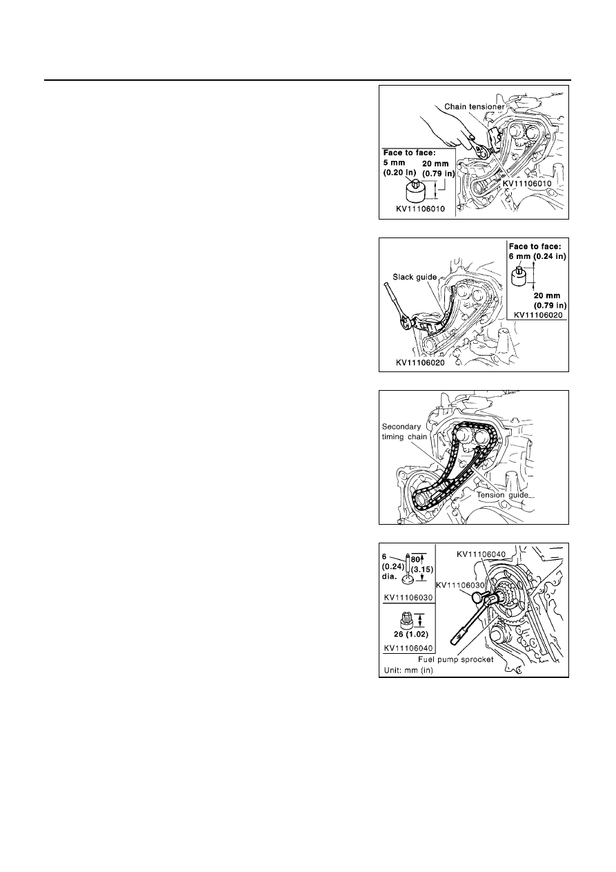
Using a hexagon-head wrench [face to face 5 mm (0.20 in)
SST], remove bolts to remove chain tensioner.

12. Remove timing chain slack guide.

Using a hexagon-head wrench [face to face 6 mm (0.24 in)
SST], remove bolt to remove timing chain slack guide.

13. Remove timing chain tension guide.

14. Remove secondary timing chain.

Timing chain alone can be removed without removing sprock-
ets.

15. Hold fuel pump sprocket and remove bolt.

a.

Insert positioning stopper pin (SST) into the hole 6 mm (0.24 in)
in the diameter on the fuel pump sprocket.

b.

Using a TORX wrench (SST), turn pump shaft little by little to
adjust the position of fuel pump sprocket so that the holes align.

c.

Push positioning stopper pin (SST) through pump sprocket to
fuel pump spacer to hold pump sprocket.

SBIA0227E

SBIA0228E

JEM127G

MBIA0049E

FUEL PUMP

EM-153

[YD]

C

D

E

F

G

H

I

J

K

L

M

A

EM

Insert the positioning stopper pin until its flange contacts the fuel
pump sprocket.

Remove the TORX wrench (SST).

16. Using a hexagon-head wrench [face to face 6 mm (0.24 in) SST]

remove tightening bolts of fuel pump sprocket and washer.

17. Using the sprocket holder (SST), hold the fuel pump sprocket to

prevent falling.

MBIA0050E

PBIC0945E

MBIA0074E

SBIA0217E

EM-154

[YD]

FUEL PUMP

As for the sprocket holder, install fuel pump mounting bolt
through hole of KV11106060 as shown in figure.

When the sprocket holder is installed, if the positioning stop-
per pin interferes, pull out the stopper pin approximately 10
mm (0.39 in), then install it.

After the sprocket holder is installed temporarily, insert the
extension bar (SST) and TORX socket in the three holes.
After positioning the holes, tighten the holder mounting bolts.

The thread length of the sprocket holder mounting bolts
should be approximately 15 mm (0.59 in).

Make sure that the a- and b-faces of the sprocket holder con-
tact the bottom side of the sprocket (small diameter side).

CAUTION:

Do not remove the sprocket holder until the fuel pump is
installed.

After the sprocket holder is installed, pull out the positioning
stopper pin (SST) from the fuel pump sprocket.

18. Using the extension bar [SST: whole length 43 mm (1.69 in)] and

the TORX socket (Q6-E12: commercially available), remove the
tightening bolts.

CAUTION:

Do not disassemble or adjust the fuel pump excepting the
following.

19. Remove the fuel pump toward the rear of the engine.

NOTE:
The seal washer of the tightening bolts cannot be reused.

CAUTION:

For removal, be careful not to drop the seal washer into the
engine.

SBIA0218E

MBIA0075E

SBIA0220E

MBIA0076E

FUEL PUMP

EM-155

[YD]

C

D

E

F

G

H

I

J

K

L

M

A

EM

20. Remove adjusting shim.

21. Attach a suitable tool in the M8 bolt hole on coupling.

22. Loosen sprocket nut with the TORX wrench (SST).

23. Remove coupling with a suitable puller.

24. Remove spacer from fuel pump.

INSPECTION AFTER REMOVAL
Timing Chain

Check for cracks and excessive wear at roller links. Replace
chain if necessary.

INSTALLATION

1.

Install new oil seal to the spacer.

2.

Install fuel pump to the spacer.

MBIA0013E

MBIA0014E

SEM984C

MBIA0045E


Content   ..  872  873  874  875   ..