Nissan Almera Tino V10. Manual - part 846


  Index      Nissan     Nissan Almera Tino V10 - Service Manual (2003 year)


Search            


Content   ..  844  845  846  847   ..


Nissan Almera Tino V10. Manual - part 846


EM-40

[QG]

CAMSHAFT

CAUTION:

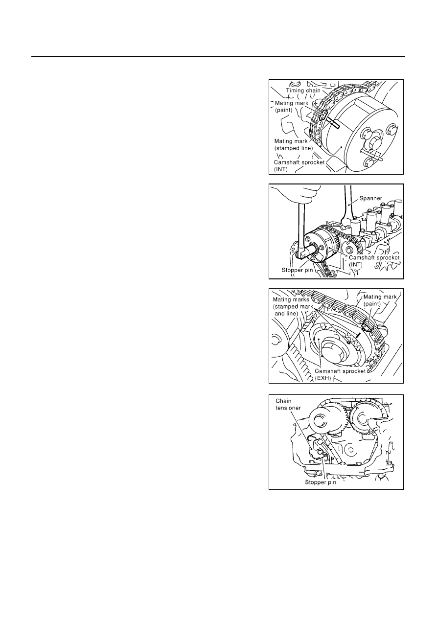
Stopper pin is easily detached. Secure it with vinyl tape to prevent detachment.

a.

Install timing chain by aligning its mating mark (marked when
timing chain is removed) with mark on camshaft sprocket.

Align dowel pin on camshaft front surface and pinhole on
sprocket backside, then install.

b.

While holding hexagonal part of camshaft with a spanner,
tighten intake camshaft sprocket mounting bolts.

Make sure that stopper pin is not detached.

6.

Install exhaust camshaft sprocket as follows.

a.

Install timing chain by aligning its mating mark (marked when
timing chain is removed) with mark on camshaft sprocket.

Align dowel pin on camshaft front surface and pinhole on
sprocket, then install.

b.

While holding hexagonal part of camshaft with a spanner,
tighten exhaust camshaft sprocket mounting bolts.

NOTE:
Tightening torque is different from intake side tightening torque.

c.

Make sure that mating marks on intake/exhaust camshaft
sprockets and mating mark on timing chain are aligned.

7.

Install chain tensioner.

Hold plate and plunger with a stopper pin, then install them.

After installation, remove stopper pin and release plunger.

Make sure again that mating marks on intake/exhaust cam-
shaft sprockets and mating mark on timing chain are aligned.

MBIB0208E

MBIB0209E

MBIB0210E

MBIB0211E

CAMSHAFT

EM-41

[QG]

C

D

E

F

G

H

I

J

K

L

M

A

EM

8.

Remove stopper pin from intake camshaft sprocket.

9.

Slowly turn crankshaft pulley clockwise to set intake camshaft
sprocket to most retarded position.

Sprocket begins turning after crankshaft does. Once sprocket
starts turning, keep turning crankshaft until the vane (cam-
shaft) also begins turning. Most retarded position should now
be achieved.

Most retarded position is confirmed when stopper pin groove
is at a clockwise offset from lock pin breathing groove.

While turning crankshaft slightly more counterclockwise, con-
firm that lock pin is engaged when vane and sprocket turn
together.

10. Install cylinder head front cover.

Apply liquid gasket (Use Genuine Liquid Gasket or equiva-
lent) continuously as shown in figure.

Install it by aligning dowel pin on cylinder head.

11. Check and adjust valve clearance. Refer to

EM-44, "Valve Lifter

Clearance"

.

12. From this step, install in the reverse order of removal.

PBIC0966E

MBIB0213E

MBIB0214E

PBIC0968E

EM-42

[QG]

CAMSHAFT

INSPECTION AFTER REMOVAL
Camshaft Runout

Place a V-block on a surface plate to support No. 2 and No. 5
journals on camshaft.

CAUTION:

Do not support No. 1 journal (camshaft sprocket mounting
side), because its diameter is different from that of the other
4 journals.

Set a dial gauge vertically onto journal No. 3.

Rotate the camshaft in one direction by hand and read indication
on the gauge.

A half of reading value is actual bend.

Camshaft Cam Height

Measure with a micrometer.

Camshaft Journal Clearance

Outer Diameter of Camshaft Journal

Measure with a micrometer.

Inner Diameter of Camshaft Bracket

Tighten camshaft bracket bolts to the specified torque.

Using an inside micrometer, measure inner diameter of the cam-
shaft bracket.

Calculation of Camshaft Journal Clearance
(Oil clearance) = (Camshaft bracket inner diameter) - (Camshaft journal outer diameter)

Standard

: 0.02 mm (0.0008 in) or less

MBIB0215E

Intake

: 40.217 - 40.407 mm (1.5833 - 1.5908 in)

Exhaust

: 39.205 - 39.395 mm (1.5435 - 1.5510 in)

MBIB0216E

Standard

No. 1

: 27.935 - 27.955 mm (1.0998 - 1.1006 in) dia.

No. 2 to No. 5

: 23.935 - 23.955 mm (0.9423 - 0.9431 in) dia.

MBIB0217E

Standard

No. 1

: 28.000 - 28.021 mm (1.1024 - 1.1032 in) dia.

No. 2 to No. 5

: 24.000 - 24.021 mm (0.9449 - 0.9457 in) dia.

MBIB0218E

CAMSHAFT

EM-43

[QG]

C

D

E

F

G

H

I

J

K

L

M

A

EM

If outside the standard, refer to standard of each unit part and replace camshaft or cylinder head as appro-
priate.

NOTE:
Camshaft bracket is machined with cylinder head. Replace them as cylinder head assembly.

Camshaft End play

Position a dial gauge onto front end of camshaft in thrust direc-
tion. Read indication of dial gauge while moving camshaft back
and forth (axial direction).

If outside the standard, replace camshaft with new one. Then
measure it again.

If still outside the standard, replace cylinder head with new one.

Camshaft Sprocket Runout

Using a dial gauge, measure camshaft sprocket runout.

Valve Lifter and Adjusting Shim (Shim type)

Check surfaces of valve lifter and shim for cracks and wear.

Valve Lifter Clearance

Outer Diameter of Valve Lifter

Standard

: 0.045 - 0.086 mm (0.0018 - 0.0028 in)

Standard

Intake

: 0.070 - 0.143 mm (0.0028 - 0.0056 in)

Exhaust

: 0.115 - 0.188 mm (0.0045 - 0.0074 in)

MBIB0219E

Limit:

Intake

: 0.2 mm (0.008 in)

Exhaust

: 0.15 mm (0.0059 in)

PBIC0930E

SEM160D


Content   ..  844  845  846  847   ..