Nissan Almera Tino V10. Manual - part 814


  Index      Nissan     Nissan Almera Tino V10 - Service Manual (2003 year)


Search            


Content   ..  812  813  814  815   ..


Nissan Almera Tino V10. Manual - part 814


CAN COMMUNICATION CIRCUIT CHECK

=NLEL0656S12

1

CHECK CONNECTOR

1. Turn ignition switch OFF.
2. Disconnect the negative battery cable.
3. Check following terminals and connector of combination meter for damage, bend and loose connection (meter side,

control unit side, control module side and harness side).

I

Combination meter

I

Smart entrance control unit

I

TCM

I

ECM

I

ABS actuator and electric unit (control unit)

I

Between ECM and data link connector

OK or NG

OK

©

GO TO 2.

NG

©

Repair terminal or connector.
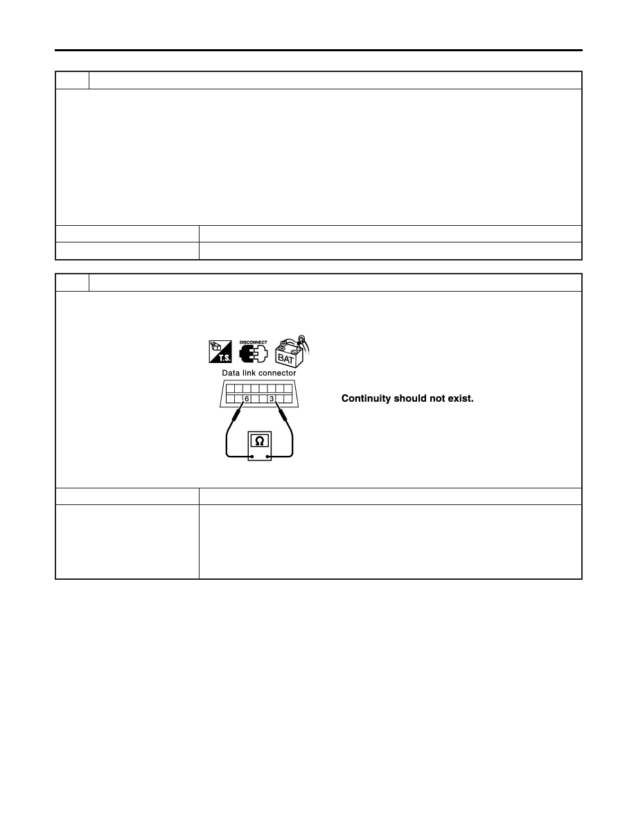
2

CHECK HARNESS FOR SHORT CIRCUIT

1. Disconnect combination meter connector, smart entrance control unit connector and harness connector M82 (LHD mod-

els) or harness connector M80 (RHD models).

2. Check continuity between data link connector M6 terminals 6 (L) and 3 (R).

SEL816Y

OK or NG

OK

©

GO TO 3.

NG

©

I

Repair harness between data link connector and harness connector M82 (LHD mod-
els).

I

Repair harness between data link connector and harness connector M80 (RHD mod-
els).

I

Repair harness between data link connector and smart entrance control unit.

I

Repair harness between data link connector and combination meter.

CAN SYSTEM (TYPE 4)

Trouble Diagnoses (Cont’d)

EL-552

3

CHECK HARNESS FOR SHORT CIRCUIT

Check continuity between data link connector M6 terminals 6 (L), 3 (R) and ground.

SEL817Y

OK or NG

OK

©

GO TO 4.

NG

©

I

Repair harness between data link connector and harness connector M82 (LHD mod-
els).

I

Repair harness between data link connector and harness connector M80 (RHD mod-
els).

I

Repair harness between data link connector and smart entrance control unit.

I

Repair harness between data link connector and combination meter.

4

CHECK HARNESS FOR SHORT CIRCUIT

1. Disconnect ECM connector, harness connector M112 harness connector M11 (LHD models) or harness connector M80

(RHD models).

2. Check continuity between ECM harness connector M107 terminals 94 (L) and 86 (R).

SEL820Y

OK or NG

OK

©

GO TO 5.

NG

©

I

Repair harness between ECM and harness connector M11 (LHD models).

I

Repair harness between ECM and harness connector M80 (RHD models).

I

Repair harness between ECM and harness connector M112.

GI

MA

EM

LC

EC

FE

CL

MT

AT

AX

SU

BR

ST

RS

BT

HA

SC

IDX

CAN SYSTEM (TYPE 4)

Trouble Diagnoses (Cont’d)

EL-553

5

CHECK HARNESS FOR SHORT CIRCUIT

Check continuity between ECM harness connector M112 terminals 94 (L), 86 (R) and ground.

SEL821Y

OK or NG

OK

©

GO TO 6.

NG

©

I

Repair harness between ECM and harness connector M11 (LHD models).

I

Repair harness between ECM and harness connector M80 (RHD models).

I

Repair harness between ECM and harness connector M112.

6

CHECK HARNESS FOR SHORT CIRCUIT

1. Disconnect TCM connector.
2. Check continuity between TCM harness connector F71 terminals 5 (L) and 6 (R).

YEL428E

OK or NG

OK

©

GO TO 7.

NG

©

Repair harness between TCM and harness connector F73.

CAN SYSTEM (TYPE 4)

Trouble Diagnoses (Cont’d)

EL-554

7

CHECK HARNESS FOR SHORT CIRCUIT

Check continuity between TCM harness connector F71 terminals 5 (L), 6 (R) and ground.

YEL429E

OK or NG

OK

©

GO TO 8.

NG

©

Repair harness between TCM and harness connector F73.

8

CHECK HARNESS FOR SHORT CIRCUIT

1. Disconnect harness connector ABS actuator and electric unit (control unit).
2. Check continuity between ABS actuator and electric unit (control unit) harness connector E142 terminals 26 (L) and 15

(R).

YEL455E

OK or NG

OK

©

GO TO 9.

NG

©

I

Repair harness between ABS actuator and electric unit (control unit) and harness con-
nector E125. (LHD models)

I

Repair harness between ABS actuator and electric unit (control unit) and harness con-
nector E106. (LHD models)

I

Repair harness between ABS actuator and electric unit (control unit) and harness con-
nector E145. (RHD models)

GI

MA

EM

LC

EC

FE

CL

MT

AT

AX

SU

BR

ST

RS

BT

HA

SC

IDX

CAN SYSTEM (TYPE 4)

Trouble Diagnoses (Cont’d)

EL-555


Content   ..  812  813  814  815   ..