Nissan Almera Tino V10. Manual - part 798
3
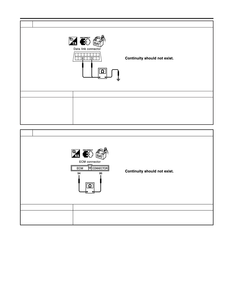
CHECK HARNESS FOR SHORT CIRCUIT
Check continuity between data link connector M6 terminals 6 (L), 3 (R) and ground.
SEL817Y
OK or NG
OK
©
GO TO 4.
NG
©
I
Repair harness between data link connector and harness connector M82 (LHD mod-
els).
I
Repair harness between data link connector and harness connector M80 (RHD mod-
els).
I
Repair harness between data link connector and smart entrance control unit.
I
Repair harness between data link connector and combination meter.
4
CHECK HARNESS FOR SHORT CIRCUIT
1. Disconnect ECM connector, harness connector M112 and harness connector M11 (LHD models).
2. Check continuity between ECM harness connector M107 terminals 94 (L) and 86 (R).
SEL820Y
OK or NG
OK
©
GO TO 5.
NG
©
I
Repair harness between ECM and harness connector M11 (LHD models).
I
Repair harness between ECM and harness connector M80 (RHD models).
I
Repair harness between ECM and harness connector M112.
CAN SYSTEM (TYPE 1)
Trouble Diagnoses (Cont’d)
EL-488