Nissan Almera Tino V10. Manual - part 722
SEL263
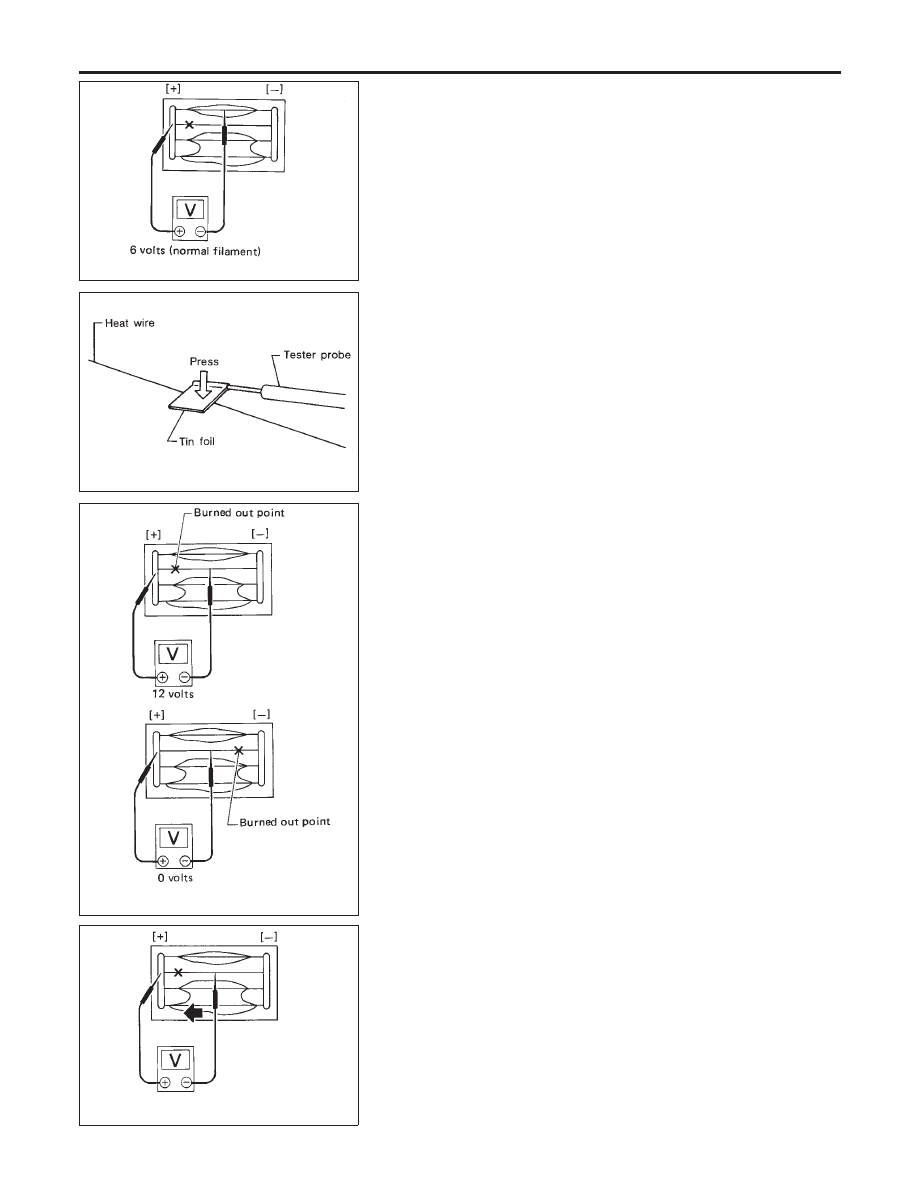
Filament Check
=NLEL0077
1.
Attach probe circuit tester (in volt range) to middle portion of
each filament.
SEL122R
I
When measuring voltage, wrap tin foil around the top of
the negative probe. Then press the foil against the wire
with your finger.
SEL265
2.
If a filament is burned out, circuit tester registers 0 or 12 volts.
SEL266
3.
To locate burned out point, move probe to left and right along
filament. Test needle will swing abruptly when probe passes
the point.
REAR WINDOW DEFOGGER
Filament Check
EL-184