Index Nissan Nissan Almera Tino V10 - Service Manual (2003 year)
Search
Content .. 713 714 715 716 ..
Nissan Almera Tino V10. Manual - part 715
RHD MODELS
NLEL0462S02
YEL972D
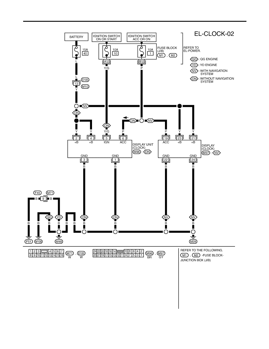
CLOCK
Wiring Diagram — CLOCK — (Cont’d)
EL-156