Index Nissan Nissan Almera Tino V10 - Service Manual (2003 year)
Search
Content .. 693 694 695 696 ..
Nissan Almera Tino V10. Manual - part 695
YEL948D
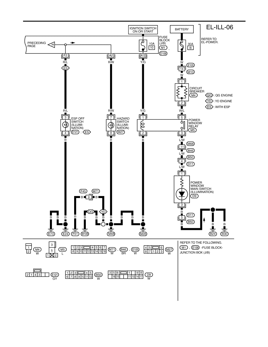
ILLUMINATION
Wiring Diagram — ILL — (Cont’d)
EL-76