Index Nissan Nissan Almera Tino V10 - Service Manual (2003 year)
Search
Content .. 691 692 693 694 ..
Nissan Almera Tino V10. Manual - part 693
YEL571E
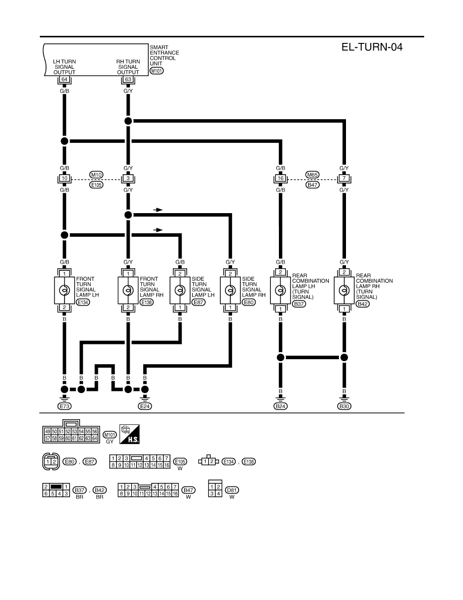
TURN SIGNAL AND HAZARD WARNING LAMPS
Wiring Diagram — TURN — (Cont’d)
EL-68