Nissan Almera Tino V10. Manual - part 654
EC-1442
[YD (WITHOUT EURO-OBD)]
DTC P0686 ECM RELAY
Diagnostic Procedure
EBS014YM
1.
CHECK ECM OUTPUT SIGNAL CIRCUIT FOR SHORT TO GROUND
1.
Turn ignition switch OFF.
2.
Disconnect ECM harness connector.
3.
Check harness continuity between ECM terminals 105, 113 and ground.
Refer to Wiring Diagram.
OK or NG
OK
>> GO TO 2.
NG
>> Repair short to ground in harness or connectors.
2.
CHECK ECM INPUT SIGNAL CIRCUIT FOR OPEN AND SHORT
1.
Disconnect ECM relay.
2.
Check harness continuity between ECM terminals 119, 120 and
ECM relay terminal 7. Refer to Wiring Diagram.
3.
Also check harness for short to ground and short to power.
OK or NG
OK
>> GO TO 3.
NG
>> Repair open circuit or short to ground or short to power
in harness or connectors.
3.
CHECK ECM RELAY
Refer to
EC-1442, "Component Inspection"
.
OK or NG
OK
>> GO TO 4.
NG
>> Replace ECM relay.
4.
CHECK INTERMITTENT INCIDENT
Refer to
EC-1309, "TROUBLE DIAGNOSIS FOR INTERMITTENT INCIDENT"
.
>> INSPECTION END
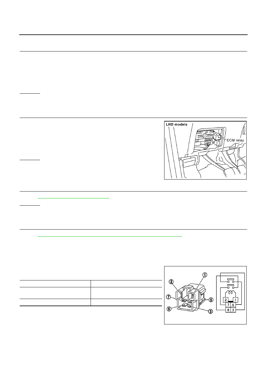
Component Inspection
EBS014YN
ECM RELAY
1.
Apply 12V direct current between ECM relay terminals 1 and 2.
2.
Check continuity between relay terminals 3 and 5, 6 and 7.
3.
If NG, replace ECM relay.
Continuity should not exist.
Continuity should exist.
MBIB0922E
Condition
Continuity
12V direct current supply between ter-
minals 1 and 2
Yes
OFF
No
PBIB0077E