Nissan Almera Tino V10. Manual - part 647


  Index      Nissan     Nissan Almera Tino V10 - Service Manual (2003 year)


Search            


Content   ..  645  646  647  648   ..


Nissan Almera Tino V10. Manual - part 647


EC-1414

[YD (WITHOUT EURO-OBD)]

DTC P0341 CMP SENSOR

DTC Confirmation Procedure

EBS014XB

NOTE:
If DTC Confirmation Procedure has been previously conducted, always turn ignition switch OFF and wait at
least 10 seconds before conducting the next test.

WITH CONSULT-II

1.

Turn ignition switch ON.

2.

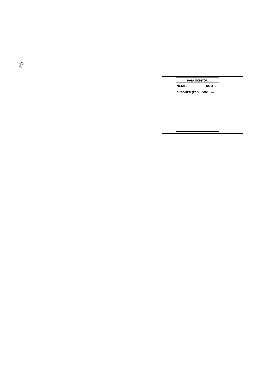
Select “DATA MONITOR” mode with CONSULT-II.

3.

Start engine and let it idle for at least 5 seconds.
If engine could not start, keep ignition switch at START position
for 5 seconds.

4.

If DTC is detected, go to

EC-1416, "Diagnostic Procedure"

.

SEF817Y

DTC P0341 CMP SENSOR

EC-1415

[YD (WITHOUT EURO-OBD)]

C

D

E

F

G

H

I

J

K

L

M

A

EC

Wiring Diagram

EBS014XC

YEC505A

EC-1416

[YD (WITHOUT EURO-OBD)]

DTC P0341 CMP SENSOR

Diagnostic Procedure

EBS014XD

1.

CHECK STARTING SYSTEM

Turn ignition switch to START position.

Yes or No

Yes

>> GO TO 2.

No

>> Check starting system. (Refer to SC-16, “STARTING SYSTEM”.)

2.

CHECK GROUND CONNECTIONS

1.

Turn ignition switch OFF.

2.

Loosen and retighten body ground screw. Refer to

EC-1317,

"Ground Inspection"

.

OK or NG

OK

>> GO TO 3.

NG

>> Repair or replace ground connection.

3.

CHECK CMP SENSOR POWER SUPPLY CIRCUIT

1.

Disconnect camshaft position (CMP) sensor harness connector.

2.

Turn ignition switch ON.

3.

Check voltage between CMP sensor terminal 1 and ground with
CONSULT-II or tester.

OK or NG

OK

>> GO TO 4.

NG

>> Repair open circuit or short to ground or short to power

in harness or connectors.

Does the engine turn over?

Does the starter motor operate?

MBIB0915E

MBIB0907E

Voltage: Approximately 5.3V

MBIB1095E

DTC P0341 CMP SENSOR

EC-1417

[YD (WITHOUT EURO-OBD)]

C

D

E

F

G

H

I

J

K

L

M

A

EC

4.

CHECK CMP SENSOR GROUND CIRCUIT FOR OPEN AND SHORT

1.

Turn ignition switch OFF.

2.

Disconnect ECM harness connector.

3.

Check harness continuity between ECM terminal 66 and CMP sensor terminal 2.
Refer to Wiring Diagram.

4.

Also check harness for short to ground and short to power.

OK or NG

OK

>> GO TO 5.

NG

>> Repair open circuit or short to ground or short to power in harness or connectors.

5.

CHECK CMP SENSOR INPUT SIGNAL CIRCUIT FOR OPEN AND SHORT

1.

Check harness continuity between ECM terminal 47 and CMP sensor terminal 3.
Refer to Wiring Diagram.

2.

Also check harness for short to ground or short to power.

OK or NG

OK

>> GO TO 6.

NG

>> Repair open circuit or short to ground or short to power in harness or connectors.

6.

CHECK CAMSHAFT POSITION SENSOR

Refer to

EC-1418, "Component Inspection"

.

OK or NG

OK

>> GO TO 7.

NG

>> Replace camshaft position sensor.

7.

CHECK CAMSHAFT (EXHAUST)

Check the following.

Accumulation of debris to the signal plate of camshaft rear end

Chipping signal plate of camshaft rear end

OK or NG

OK

>> GO TO 8.

NG

>> Remove debris and clean the signal plate of camshaft

rear end or replace camshaft.

8.

CHECK INTERMITTENT INCIDENT

Refer to

EC-1309, "TROUBLE DIAGNOSIS FOR INTERMITTENT INCIDENT"

.

>> INSPECTION END

Continuity should exist.

Continuity should exist.

MBIB0990E


Content   ..  645  646  647  648   ..