Nissan Almera Tino V10. Manual - part 641


  Index      Nissan     Nissan Almera Tino V10 - Service Manual (2003 year)


Search            


Content   ..  639  640  641  642   ..


Nissan Almera Tino V10. Manual - part 641


EC-1390

[YD (WITHOUT EURO-OBD)]

DTC P0234 TC SYSTEM

Component Inspection

EBS014W8

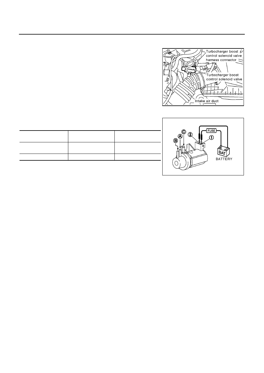
TURBOCHARGER BOOST CONTROL SOLENOID VALVE

1.

Disconnect turbocharger boost control solenoid valve harness
connector.

2.

Apply 12V direct current between turbocharger boost control solenoid valve terminals.

3.

Check air passage continuity of turbocharger boost control sole-
noid valve under the following conditions.

Operation takes less than 1 second.

If NG, replace turbocharger boost control solenoid valve.

MBIB0921E

CONDITIONS

Air passage continuity

between and B

Air passage continuity

between and C

12V direct current supply
between terminals and 2

Yes

No

No supply

No

Yes

MBIB0996E

DTC P0237, P0238 TC BOOST SENSOR

EC-1391

[YD (WITHOUT EURO-OBD)]

C

D

E

F

G

H

I

J

K

L

M

A

EC

DTC P0237, P0238 TC BOOST SENSOR

PFP:22365

Component Description

EBS014W9

The turbocharger boost sensor detects pressure in the exit side of
the charge air cooler. The sensor output voltage to the ECM
increases as pressure increases.

CONSULT-II Reference Value in Data Monitor Mode

EBS014WA

Specification data are reference values.

ECM Terminals and Reference Value

EBS014WB

Specification data are reference values, and are measured between each terminal and ground.

CAUTION:

Do not use ECM ground terminals when measuring input/output voltage. Doing so may damage the
ECM's transistor. Use a ground other than ECM terminals, such as the ground.

MBIB0614E

MBIB0899E

MONITOR ITEM

CONDITION

SPECIFICATION

INT/M PRES SE [kPa]

Engine: After warming up

Air conditioner switch: OFF

Shift lever: Neutral position

No-load

Idle

Approx. 100 kPa

2,800 rpm

Approx. 126 kPa

4,000 rpm

Approx. 106 kPa

TERMI-

NAL

NO.

WIRE

COLOR

ITEM

CONDITION

DATA

(DC Voltage)

52

Y

Turbocharger boost sensor

[Engine is running]

Warm-up condition

Idle speed

2.3 - 2.6V

[Engine is running]

Warm-up condition

Engine speed is 2,000 rpm

2.5 - 2.8V

64

W

Turbocharger boost sensor
power supply

[Ignition switch ON]

Approximately 5.3V

71

B

Turbocharger boost sensor
ground

[Ignition switch ON]

Approximately 0.3V

EC-1392

[YD (WITHOUT EURO-OBD)]

DTC P0237, P0238 TC BOOST SENSOR

On Board Diagnosis Logic

EBS014WC

The MI will not light up for these self-diagnoses.

DTC Confirmation Procedure

EBS014WD

NOTE:
If DTC Confirmation Procedure has been previously conducted, always turn ignition switch OFF and wait at
least 10 seconds before conducting the next test.

WITH CONSULT-II

1.

Turn ignition switch ON.

2.

Select “DATA MONITOR” mode with CONSULT-II.

3.

Wait at least 5 seconds.

4.

If DTC is detected, go to

EC-1394, "Diagnostic Procedure"

.

DTC No.

Trouble diagnosis name

DTC detecting condition

Possible cause

P0237

Turbocharger boost sensor
circuit low input

An excessively low voltage from the sensor is
sent to ECM.

Harness or connectors
(The sensor circuit is open or shorted.)

Turbocharger boost sensor

P0238

Turbocharger boost sensor
circuit high input

An excessively high voltage from the sensor is
sent to ECM.

SEF817Y

DTC P0237, P0238 TC BOOST SENSOR

EC-1393

[YD (WITHOUT EURO-OBD)]

C

D

E

F

G

H

I

J

K

L

M

A

EC

Wiring Diagram

EBS014WE

YEC503A


Content   ..  639  640  641  642   ..