Nissan Almera Tino V10. Manual - part 612


  Index      Nissan     Nissan Almera Tino V10 - Service Manual (2003 year)


Search            


Content   ..  610  611  612  613   ..


Nissan Almera Tino V10. Manual - part 612


EC-1274

[YD (WITHOUT EURO-OBD)]

ON BOARD DIAGNOSTIC (OBD) SYSTEM

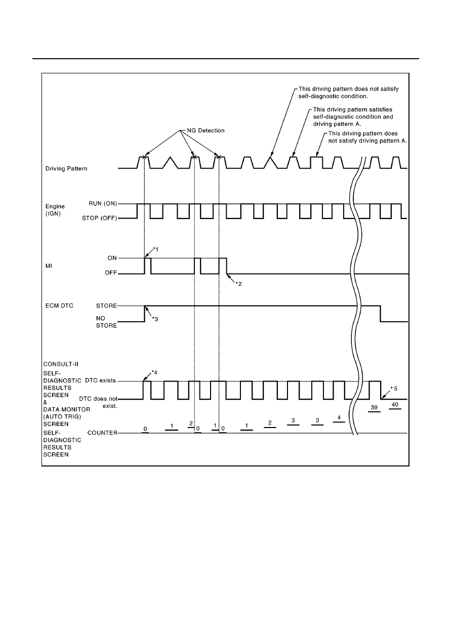
Relationship Between MI, DTC, CONSULT-II and Driving Patterns

*1: When a malfunction is detected, MI

will light up.

*2: MI will not light up after ignition

switch is turned OFF.

*3: When a malfunction is detected for

the first time, the DTC will be stored
in ECM.

*4: Other screens except SELF-DIAG-

NOSTIC RESULTS & DATA MONI-
TOR (AUTO TRIG) cannot display
the malfunction. DATA MONITOR
(AUTO TRIG) can display the mal-
function at the moment it is detected.

*5: The DTC will not be displayed any

longer after vehicle is driven 40 times
(Driving pattern A) without the same
malfunction. (The DTC still remain in
ECM.)

MBIB0622E

ON BOARD DIAGNOSTIC (OBD) SYSTEM

EC-1275

[YD (WITHOUT EURO-OBD)]

C

D

E

F

G

H

I

J

K

L

M

A

EC

Driving Pattern A

The A counter will be cleared when the malfunction is detected regardless of (1) - (4).

The A counter will be counted up when (1) - (4) are satisfied without the same malfunction.

The DTC will not be displayed after the A counter reaches 40.

MBIB0923E

EC-1276

[YD (WITHOUT EURO-OBD)]

TROUBLE DIAGNOSIS

TROUBLE DIAGNOSIS

PFP:00004

Trouble Diagnosis Introduction

EBS014SS

INTRODUCTION

The engine has an ECM to control major systems such as fuel injec-
tion control, fuel injection timing control, glow control system, etc.
The ECM accepts input signals from sensors and instantly actuators.
It is essential that both input and output signals are proper and sta-
ble. At the same time, it is important that there are no malfunctions
such as vacuum leaks, or other malfunctions with the engine.

It is much more difficult to diagnose a malfunction that occurs inter-
mittently rather than continuously. Most intermittent malfunctions are
caused by poor electric connections or improper wiring. In this case,
careful checking of suspected circuits may help prevent the replace-
ment of good parts.

A visual check only may not find the cause of the incidents. A road
test with CONSULT-II or a circuit tester connected should be per-
formed. Follow the

EC-1277, "WORK FLOW"

.

Before undertaking actual checks, take a few minutes to talk with a
customer who approaches with a driveability complaint. The cus-
tomer can supply good information about such incidents, especially
intermittent ones. Find out what symptoms are present and under
what conditions they occur. A Diagnostic Worksheet like the example
on next page should be used.
Start your diagnosis by looking for conventional incidents first. This
will help troubleshoot driveability incidents on an electronically con-
trolled engine vehicle.

MEF036D

SEF233G

SEF234G

TROUBLE DIAGNOSIS

EC-1277

[YD (WITHOUT EURO-OBD)]

C

D

E

F

G

H

I

J

K

L

M

A

EC

WORK FLOW

*1

If time data of “SELF-DIAG
RESULTS” is other than “0”, perform

EC-1309, "TROUBLE DIAGNOSIS
FOR INTERMITTENT INCIDENT"

.

*2

If the incident cannot be verified, per-
form

EC-1309, "TROUBLE DIAGNO-

SIS FOR INTERMITTENT
INCIDENT"

.

*3

If the on board diagnostic system
cannot be performed, check main
power supply and ground circuit.
Refer to

EC-1310, "MAIN POWER

SUPPLY AND GROUND CIRCUIT"

.

*4

If malfunctioning part cannot be
detected, perform

EC-1309, "TROU-

BLE DIAGNOSIS FOR INTERMIT-
TENT INCIDENT"

.

PBIB0477E


Content   ..  610  611  612  613   ..