Nissan Almera Tino V10. Manual - part 586


  Index      Nissan     Nissan Almera Tino V10 - Service Manual (2003 year)


Search            


Content   ..  584  585  586  587   ..


Nissan Almera Tino V10. Manual - part 586


EC-1170

[YD (WITH EURO-OBD)]

DTC P0652, P0653 SENSOR POWER SUPPLY

Diagnostic Procedure

EBS013EY

1.

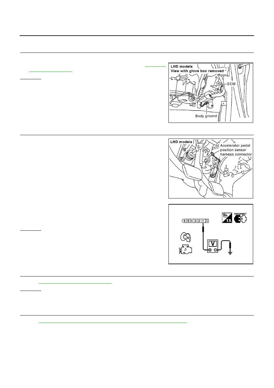
CHECK GROUND CONNECTIONS

1.

Turn ignition switch OFF.

2.

Loosen and retighten body ground screw. Refer to

EC-1010,

"Ground Inspection"

.

OK or NG

OK

>> GO TO 2.

NG

>> Repair or replace ground connection.

2.

CHECK APP SENSOR 2 POWER SUPPLY CIRCUIT

1.

Disconnect accelerator pedal position (APP) sensor harness
connector.

2.

Turn ignition switch ON.

3.

Check voltage between APP sensor terminal 1 and ground with
CONSULT-II or tester.

OK or NG

OK

>> GO TO 3.

NG

>> Repair open circuit or short to ground or short to power

in harness or connectors.

3.

CHECK APP SENSOR

Refer to

EC-1171, "Component Inspection"

.

OK or NG

OK

>> GO TO 4.

NG

>> Replace accelerator pedal assembly.

4.

CHECK INTERMITTENT INCIDENT

Refer to

EC-1002, "TROUBLE DIAGNOSIS FOR INTERMITTENT INCIDENT"

.

>> INSPECTION END

MBIB0915E

MBIB0904E

Voltage: Approximately 5.3V

PBIB0812E

DTC P0652, P0653 SENSOR POWER SUPPLY

EC-1171

[YD (WITH EURO-OBD)]

C

D

E

F

G

H

I

J

K

L

M

A

EC

Component Inspection

EBS013EZ

ACCELERATOR PEDAL POSITION SENSOR

1.

Reconnect all harness connectors disconnected.

2.

Turn ignition switch ON.

3.

Check voltage between ECM terminals 83 (APP sensor 1 sig-
nal), 91 (APP sensor 2 signal) and engine body under the fol-
lowing conditions.

4.

If NG, replace accelerator pedal assembly.

Removal and Installation

EBS013F0

ACCELERATOR PEDAL

Refer to FE-16, “ACCELERATOR CONTROL SYSTEM”.

Terminal

Accelerator pedal

Voltage

83

(Accelerator pedal position

sensor 1)

Fully released

0.5 - 1.0V

Fully depressed

4.2 - 5.2V

91
(Accelerator pedal position
sensor 2)

Fully released

0.4 - 0.7V

Fully depressed

2.2 - 2.7V

MBIB0615E

EC-1172

[YD (WITH EURO-OBD)]

DTC P0686 ECM RELAY

DTC P0686 ECM RELAY

PFP:25230

ECM Terminals and Reference valve

EBS013F1

Specification data are reference values and are measured between each terminal and ground.

CAUTION:

Do not use ECM ground terminals when measuring input/output voltage. Doing so may result in dam-
age to the ECM's transistor. Use a ground other than ECM terminals, such as the ground.

On Board Diagnosis Logic

EBS013F2

This self-diagnosis has the one trip detection logic.
The MI will not light up for this self-diagnosis.

DTC Confirmation Procedure

EBS013F3

NOTE:
If DTC Confirmation Procedure has been previously conducted, always turn ignition switch OFF and wait at
least 10 seconds before conducting the next test.

WITH CONSULT-II

1.

Turn ignition switch ON and then turn OFF.

2.

Wait at least 30 seconds.

3.

Turn ignition switch ON.

4.

Select “DATA MONITOR” mode with CONSULT-II.

5.

If DTC is detected, go to

EC-1174, "Diagnostic Procedure"

.

WITH GST

Follow the procedure “WITH CONSULT-II” above.

TERMI-

NAL

NO.

WIRE

COLOR

ITEM

CONDITION

DATA

(DC Voltage)

105

113

G
G

ECM relay (self-shutoff)

[Ignition switch ON]
[Ignition switch OFF]

For a few seconds after turning ignition switch
OFF

Approximately 1.2V

[Ignition switch OFF]

More than a few seconds after turning ignition
switch OFF

BATTERY VOLTAGE
(11 - 14V)

107
108

W/R
W/R

Ignition switch

[Ignition switch ON]

BATTERY VOLTAGE
(11 - 14V)

119

120

R
R

Power supply for ECM

[Ignition switch ON]

BATTERY VOLTAGE
(11 - 14V)

DTC No.

Trouble diagnosis name

DTC detecting condition

Possible cause

P0686

ECM relay circuit

ECM detects ECM relay is stuck closed even if
ignition switch OFF.

Harness or connectors
(The ECM relay circuit is shorted.)

ECM relay

SEF817Y

DTC P0686 ECM RELAY

EC-1173

[YD (WITH EURO-OBD)]

C

D

E

F

G

H

I

J

K

L

M

A

EC

Wiring Diagram

EBS013F4

MBWA0652E


Content   ..  584  585  586  587   ..