Nissan Almera Tino V10. Manual - part 584
EC-1162
[YD (WITH EURO-OBD)]
DTC P0642, P0643 SENSOR POWER SUPPLY
DTC P0642, P0643 SENSOR POWER SUPPLY
PFP:18002
Description
EBS013EJ
The accelerator pedal position sensor is installed on the upper end
of the accelerator pedal assembly. The sensors detect the accelera-
tor pedal position and sends a signal to the ECM. The ECM uses the
signal to determine the amount of fuel to be injected.
CONSULT-II Reference Value in Data Monitor Mode
EBS013EK
Specification data are reference values.
*: This signal is converted by ECM internally. Thus, it differs from ECM terminal voltage.
ECM Terminals and Reference Value
EBS013EL
Specification data are reference values and are measured between each terminal and ground.
CAUTION:
Do not use ECM ground terminals when measuring input/output voltage. Doing so may result in dam-
age to the ECM's transistor. Use a ground other than ECM terminals, such as the ground.
PBIB1741E
MONITOR ITEM
CONDITION
SPECIFICATION
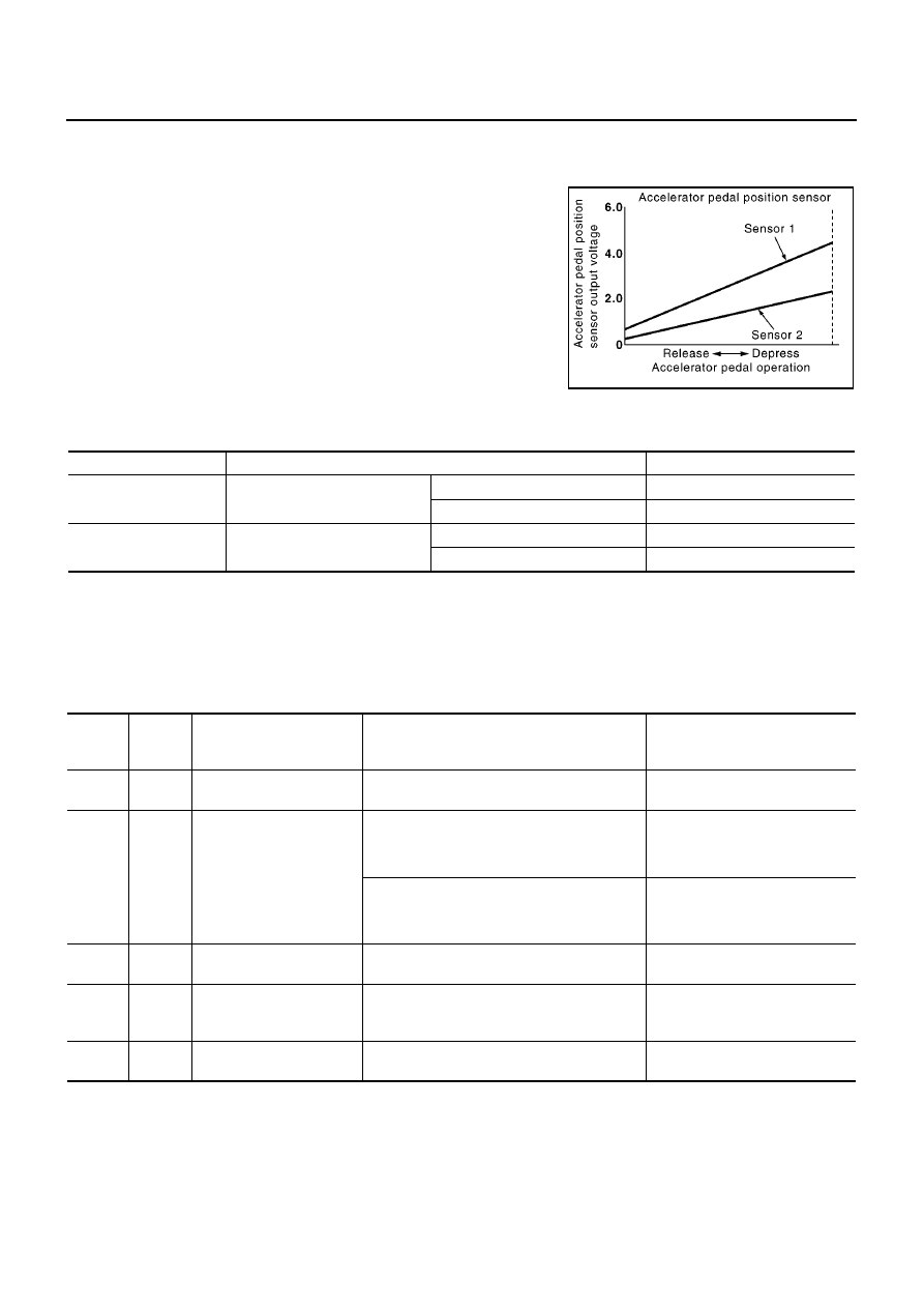
ACCEL POS SEN*
●
Ignition switch: ON
(Engine stopped)
Accelerator pedal: fully released
0.2 - 0.7V
Accelerator pedal: fully depressed
3.9 - 4.9V
ACCEL SEN 2*
●
Ignition switch: ON
(Engine stopped)
Accelerator pedal: fully released
0.1 - 0.4V
Accelerator pedal: fully depressed
1.9 - 2.4V
TERMI-
NAL
NO.
WIRE
COLOR
ITEM
CONDITION
DATA
(DC Voltage)
82
L
Accelerator pedal position
sensor 1 power supply
[Ignition switch ON]
Approximately 5.3V
83
L/R
Accelerator pedal position
sensor 1
[Ignition switch ON]
●
Engine stopped
●
Accelerator pedal: Fully released
0.5 - 1.0V
[Ignition switch ON]
●
Engine stopped
●
Accelerator pedal: Fully depressed
4.2 - 5.2V
84
L/W
Accelerator pedal position
sensor 1 ground
[Ignition switch ON]
Approximately 0.3V
85
—
Sensor ground
(Accelerator pedal posi-
tion sensor shield circuit)
[Ignition switch ON]
Approximately 0.3V
90
R
Accelerator pedal position
sensor 2 power supply
[Ignition switch ON]
Approximately 5.3V