Nissan Almera Tino V10. Manual - part 542
EC-994
[YD (WITH EURO-OBD)]
TROUBLE DIAGNOSIS
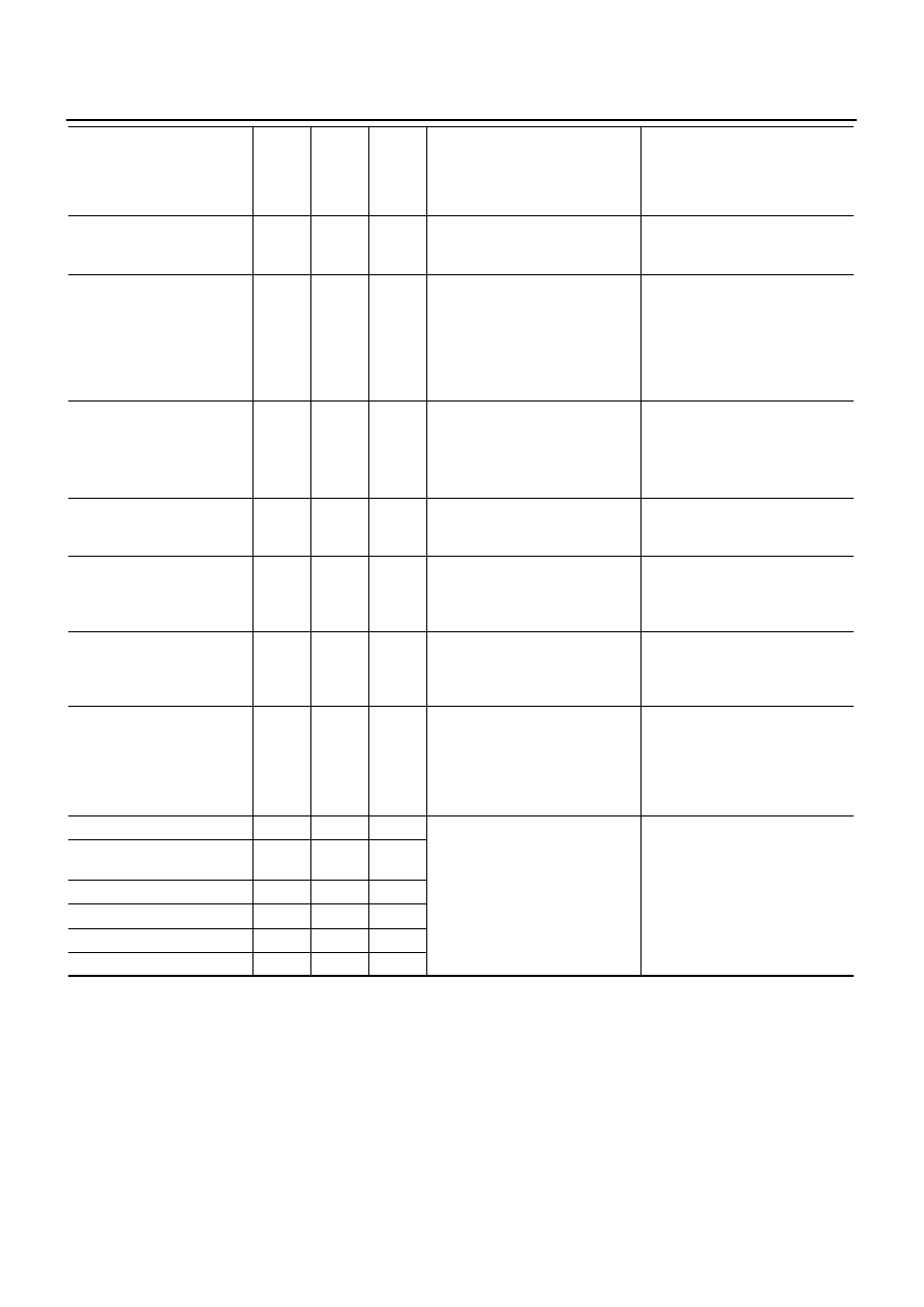
GLOW RLY [ON/OFF]
×
●
The glow relay control condition
(determined by ECM according
to the input signal) is displayed.
COOLING FAN
[LOW/HI/OFF]
×
●
Indicates the control condition of
the cooling fans (determined by
ECM according to the input sig-
nal).
LOW ... Operates at low speed.
HI ... Operates at high speed.
OFF ... Stopped
EGR VOL CON/V [step]
×
●
Indicates the EGR volume con-
trol value computed by the ECM
according to the input signals.
●
The opening becomes larger as
the value increases.
INT/A VOLUME [mg/]
●
The intake air volume computed
from the mass air flow sensor
signal is displayed.
BARO SEN [kPa]
×
×
●
The barometric pressure (deter-
mined by the signal voltage from
the absolute pressure sensor
built into the ECM) is displayed.
INT/M PRES SE [kPa]*
●
Turbocharger boost (determined
by the signal voltage from the
turbocharger boost sensor) is
displayed.
CYL COUNT [1/2/3/4]
●
The cylinder being injected is
displayed.
1 ... Cylinder No.1 is injected.
2 ... Cylinder No.2 is injected.
3 ... Cylinder No.3 is injected.
4 ... Cylinder No.4 is injected.
Voltage [V]
Voltage, frequency, duty cycle or
pulse width measured by the
probe.
Only “#” is displayed if item is
unable to be measured.
Figures with “#”s are temporary
ones.
They are the same figures as an
actual piece of data which was
just previously measured. [Hz] or
[%]
Frequency [msec], [Hz] or
[%]
DUTY-HI
DUTY-LOW
PLS WIDTH-HI
PLS WIDTH-LOW
MONITOR ITEM
ECM
INPUT
SIG-
NAL
MAIN
SIG-
NALS
CAN
DIAG
SUP-
PORT
MNTR
CONDITION
SPECIFICATION