Nissan Almera Tino V10. Manual - part 529
EC-942
[YD (WITH EURO-OBD)]
PRECAUTIONS
PRECAUTIONS
PFP:00001
Precautions for Supplemental Restraint System (SRS) “AIR BAG” and “SEAT
BELT PRE-TENSIONER”
EBS0137K
The Supplemental Restraint System such as “AIR BAG” and “SEAT BELT PRE-TENSIONER”, used along
with a front seat belt, helps to reduce the risk or severity of injury to the driver and front passenger for certain
types of collision. Information necessary to service the system safely is included in the SRS and SB section of
this Service Manual.
WARNING:
●
To avoid rendering the SRS inoperative, which could increase the risk of personal injury or death
in the event of a collision which would result in air bag inflation, all maintenance must be per-
formed by an authorized NISSAN/INFINITI dealer.
●
Improper maintenance, including incorrect removal and installation of the SRS, can lead to per-
sonal injury caused by unintentional activation of the system. For removal of Spiral Cable and Air
Bag Module, see the SRS section.
●
Do not use electrical test equipment on any circuit related to the SRS unless instructed to in this
Service Manual. SRS wiring harnesses can be identified by yellow and/or orange harnesses or
harness connectors.
On Board Diagnostic (OBD) System of Engine
EBS0137L
The ECM has an on board diagnostic system. It will light up the malfunction indicator (MI) to warn the driver of
a malfunction causing emission deterioration.
CAUTION:
●
Be sure to turn the ignition switch OFF and disconnect the battery ground cable before any repair
or inspection work. The open/short circuit of related switches, sensors, solenoid valves, etc. will
cause the MI to light up.
●
Be sure to connect and lock the connectors securely after work. A loose (unlocked) connector will
cause the MI to light up due to the open circuit. (Be sure the connector is free from water, grease,
dirt, bent terminals, etc.)
●
Certain systems and components, especially those related to OBD, may use a new style slide-
locking type harness connector. For description and how to disconnect, refer to EL-7, HARNESS
CONNECTOR.
●
Be sure to route and secure the harnesses properly after work. The interference of the harness
with a bracket, etc. may cause the MI to light up due to the short circuit.
●
Be sure to connect rubber tubes properly after work. A misconnected or disconnected rubber tube
may cause the MI to light up due to the malfunction of the fuel system, etc.
●
Be sure to erase the unnecessary malfunction information (repairs completed) from the ECM
before returning the vehicle to the customer.
Precautions
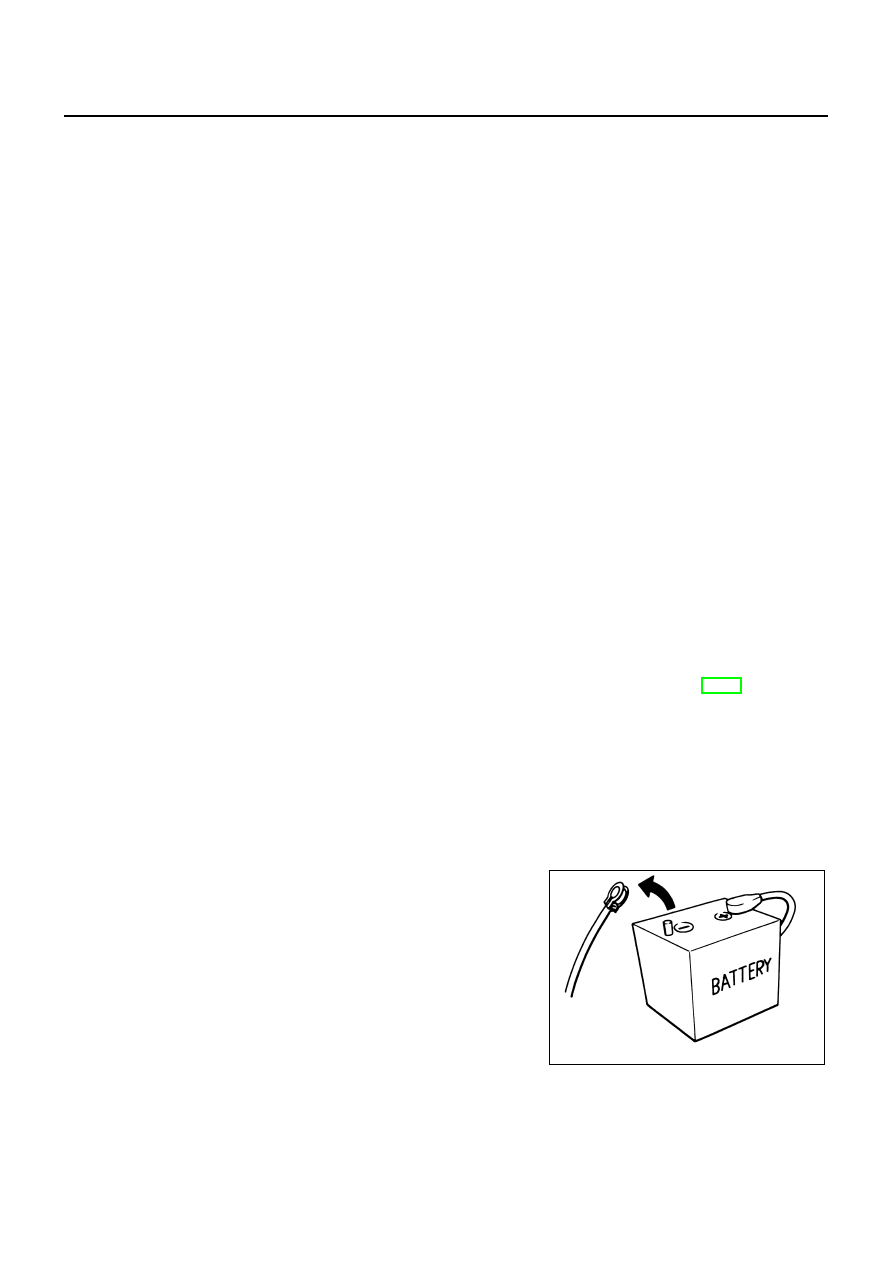
EBS0137M
●
Always use a 12 volt battery as power source.
●
Do not attempt to disconnect battery cables while engine is
running.
●
Before connecting or disconnecting the ECM harness con-
nector, turn ignition switch OFF and disconnect battery
ground cable. Failure to do so may damage the ECM
because battery voltage is applied to ECM even if ignition
switch is turned off.
●
Before removing parts, turn ignition switch OFF and then
disconnect battery ground cable.
SEF289H