Nissan Almera Tino V10. Manual - part 517
EC-894
[QG (WITHOUT EURO-OBD)]
POWER STEERING PRESSURE SENSOR
Specification data are reference values and are measured between each terminal and ground.
CAUTION:
Do not use ECM ground terminals when measuring input/output voltage. Doing so may result in dam-
age to the ECM's transistor. Use a ground other than ECM terminals, such as the ground.
Diagnostic Procedure
EBS00R3A
1.
INSPECTION START
Do you have CONSULT-II?
Yes or No
Yes
>> GO TO 2.
No
>> GO TO 3.
2.
CHECK POWER STEERING PRESSURE SENSOR OVERALL FUNCTION
With CONSULT-II
1.
Start engine.
2.
Check “PW/ST SIGNAL” in “DATA MONITOR” mode with CON-
SULT-II under the following conditions.
OK or NG
OK
>> INSPECTION END
NG
>> GO TO 4.
3.
CHECK POWER STEERING PRESSURE SENSOR OVERALL FUNCTION
Without CONSULT-II
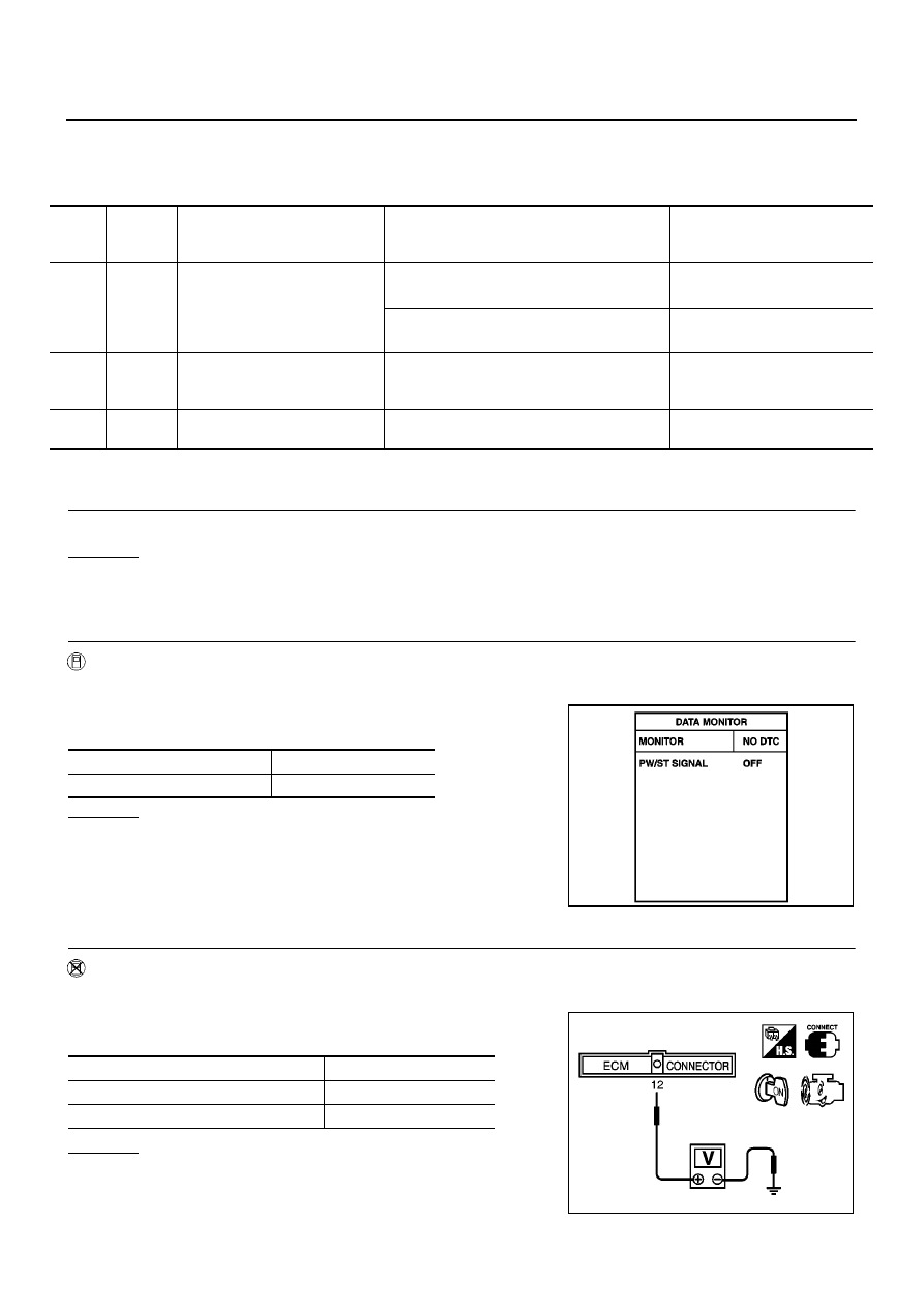
1.
Start engine.
2.
Check voltage between ECM terminal 12 and ground under the
following conditions.
OK or NG
OK
>> INSPECTION END
NG
>> GO TO 4.
TER-
MINAL
NO.
WIRE
COLOR
ITEM
CONDITION
DATA (DC Voltage)
12
L
Power steering pressure sensor
[Engine is running]
●
Steering wheel is being turned.
0.5 - 4.0V
[Engine is running]
●
Steering wheel is not being turned.
0.4 - 0.8V
57
B
Sensors' ground
(Power steering pressure sensor/
Refrigerant pressure sensor)
[Engine is running]
●
Idle speed
Approximately 0V
65
G
Sensor power supply (Power
steering pressure sensor)
[Ignition switch “ON”]
Approximately 5V
Steering in neutral position
OFF
Steering is turned
ON
PBIB0646E
Condition
Voltage
Steering wheel is being turned.
0.5 - 4.0V
Steering wheel is not being turned.
0.4 - 0.8V
MBIB0126E