Nissan Almera Tino V10. Manual - part 509
EC-862
[QG (WITHOUT EURO-OBD)]
HO2S2 (M/T MODELS)
Specification data are reference values and are measured between each terminal and ground.
CAUTION:
Do not use ECM ground terminals when measuring input/output voltage. Doing so may result in dam-
age to the ECM's transistor. Use a ground other than ECM terminals, such as the ground.
Diagnostic Procedure
EBS00R2L
1.
CHECK OVERALL FUNCTION-I
1.
Start engine and warm it up to the normal operating temperature.
2.
Turn ignition switch “OFF” and wait at least 10 seconds.
3.
Start engine and keep the engine speed between 3,500 and 4,000 rpm for at least one minute under no
load.
4.
Let engine idle for one minute.
5.
Set voltmeter probes between ECM terminal 16 (HO2S2 signal) and ground.
6.
Check the voltage while revving up to 4,000 rpm under no load
at least 10 times. (Depress and release the accelerator pedal as
quickly as possible.)
OK or NG
OK
>> INSPECTION END
NG
>> GO TO 2.
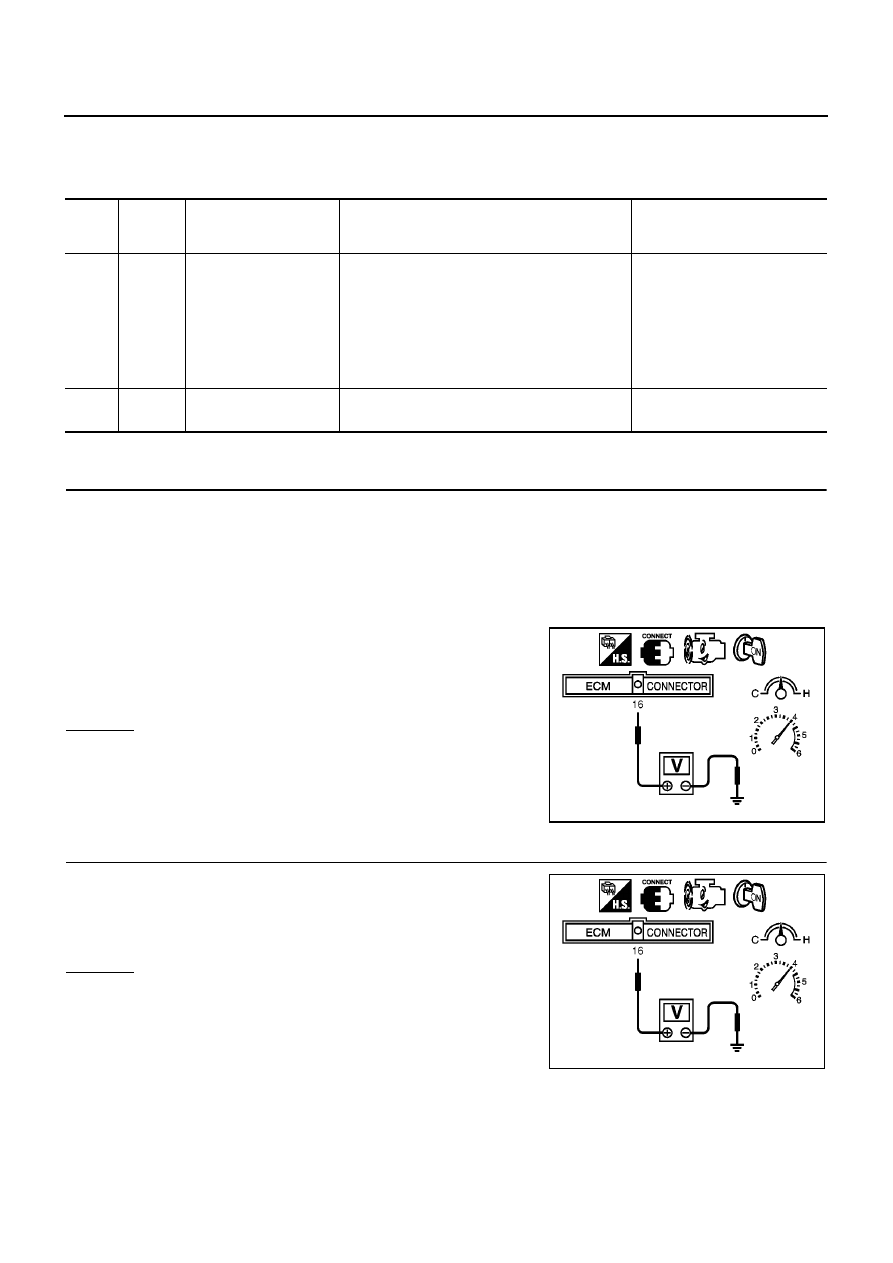
2.
CHECK OVERALL FUNCTION-II
Keep engine at idle for 10 minutes, then check the voltage between
ECM terminal 16 and ground, or check voltage when coasting 80
km/h (50 MPH) in 3rd gear position.
OK or NG
OK
>> INSPECTION END
NG
>> GO TO 3.
TER-
MINAL
NO.
WIRE
COLOR
ITEM
CONDITION
DATA (DC Voltage)
16
W
Heated oxygen sensor 2
[Engine is running]
●
Warm-up condition
●
Engine speed is 3,000 rpm quickly after the fol-
lowing conditions are met.
–
Keeping the engine speed between 3,500 and
4,000 rpm for one minute and at idle for one
minute under no load.
0 - Approximately 1.0V
74
B
Sensors' ground
(Heated oxygen sensor)
[Engine is running]
●
Idle speed
Approximately 0V
The voltage does not remain in the range of 0.2 to 0.4V
MBIB0020E
The voltage does not remain in the range of 0.2 to 0.4V
MBIB0020E