Nissan Almera Tino V10. Manual - part 487
EC-774
[QG (WITHOUT EURO-OBD)]
DTC P1124, P1126 THROTTLE CONTROL MOTOR RELAY
Component Inspection
EBS00QZW
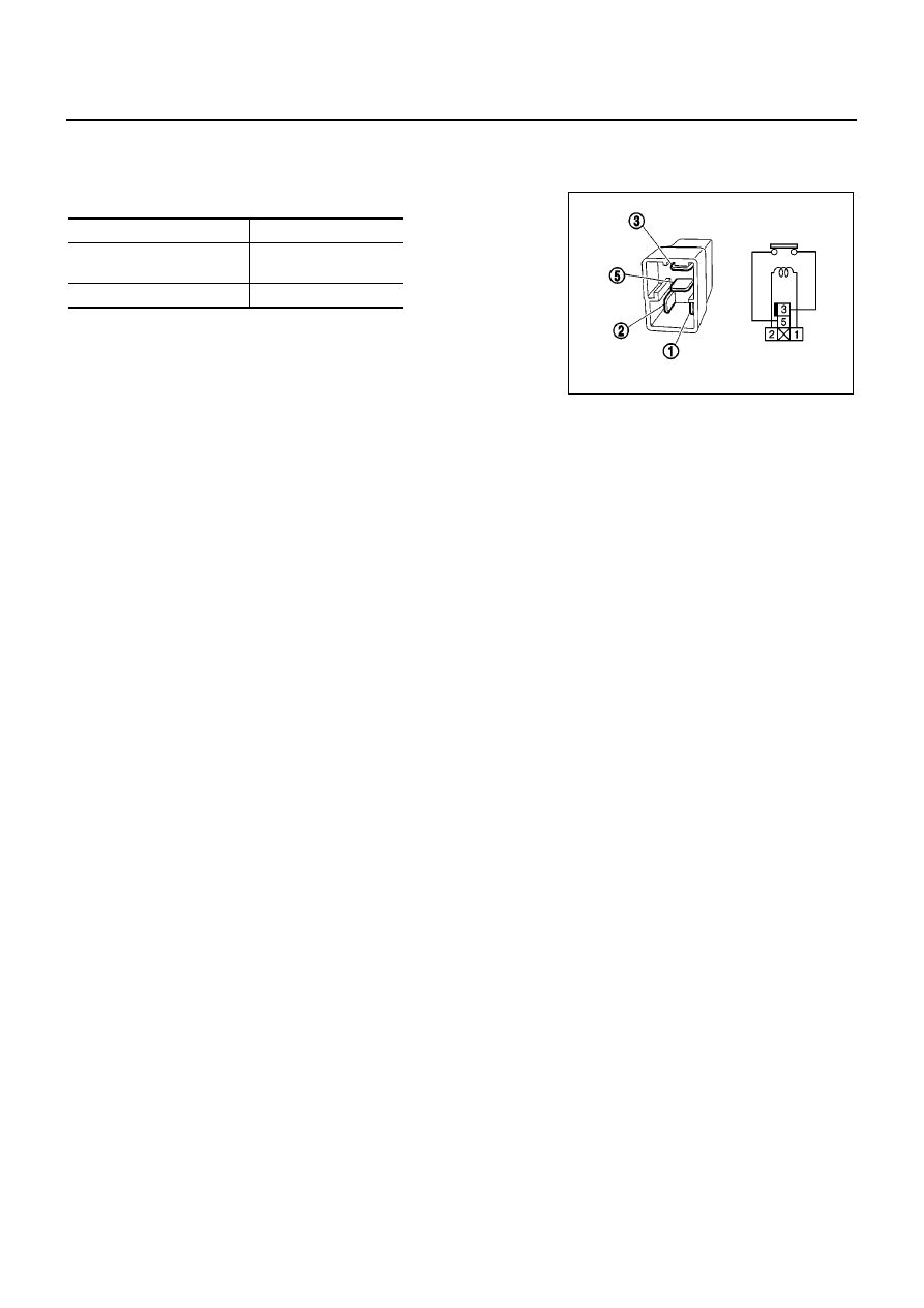
THROTTLE CONTROL MOTOR RELAY
1.
Apply 12V direct current between relay terminals 1 and 2.
2.
Check continuity between relay terminals 3 and 5.
3.
If NG, replace throttle control motor relay.
Conditions
Continuity
12V direct current supply
between terminals 1 and 2
Yes
No current supply
No
PBIB0098E