Nissan Almera Tino V10. Manual - part 486


  Index      Nissan     Nissan Almera Tino V10 - Service Manual (2003 year)


Search            


Content   ..  484  485  486  487   ..


Nissan Almera Tino V10. Manual - part 486


EC-770

[QG (WITHOUT EURO-OBD)]

DTC P1124, P1126 THROTTLE CONTROL MOTOR RELAY

Without CONSULT-II

1.

Turn ignition switch “ON” and wait at least 1 second.

2.

Turn ignition switch “OFF”, wait at least 10 seconds and then turn “ON”.

3.

If DTC is detected, go to

EC-772, "Diagnostic Procedure"

.

PROCEDURE FOR DTC P1126
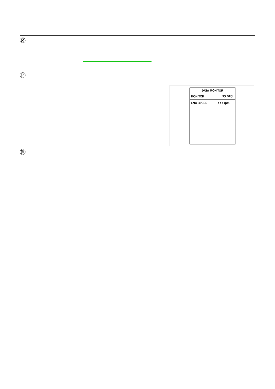
With CONSULT-II

1.

Turn ignition switch “ON” and wait at least 2 seconds.

2.

Select “DATA MONITOR” mode with CONSULT-II.

3.

Start engine and let it idle for 5 seconds.

4.

If DTC is detected, go to

EC-772, "Diagnostic Procedure"

.

Without CONSULT-II

1.

Turn ignition switch “ON” and wait at least 2 second.

2.

Start engine and let it idle for 5 seconds.

3.

Turn ignition switch “OFF”, wait at least 10 seconds and then turn “ON”.

4.

Perform “Diagnostic Test Mode II (Self-diagnostic results)” with ECM.

5.

If DTC is detected, go to

EC-772, "Diagnostic Procedure"

.

SEF058Y

DTC P1124, P1126 THROTTLE CONTROL MOTOR RELAY

EC-771

[QG (WITHOUT EURO-OBD)]

C

D

E

F

G

H

I

J

K

L

M

A

EC

Wiring Diagram

EBS00QZU

YEC464A

EC-772

[QG (WITHOUT EURO-OBD)]

DTC P1124, P1126 THROTTLE CONTROL MOTOR RELAY

Specification data are reference values and are measured between each terminal and ground.

CAUTION:

Do not use ECM ground terminals when measuring input/output voltage. Doing so may result in dam-
age to the ECM's transistor. Use a ground other than ECM terminals, such as the ground.

Diagnostic Procedure

EBS00QZV

1.

CHECK THROTTLE CONTROL MOTOR RELAY POWER SUPPLY CIRCUIT

1.

Turn ignition switch “OFF”.

2.

Disconnect throttle control motor relay.

3.

Check voltage between throttle control motor relay terminals 2, 5
and ground.

OK or NG

OK

>> GO TO 3.

NG

>> GO TO 2.

2.

DETECT MALFUNCTIONING PART

Check the following.

15A fuse

Harness for open or short between throttle control motor relay and fuse

>> Repair open circuit or short to ground or short to power in harness or connectors.

TER-

MINAL

NO.

WIRE

COLOR

ITEM

CONDITION

DATA (DC Voltage)

104

OR

Throttle control motor relay

[Ignition switch “OFF”]

BATTERY VOLTAGE
(11 - 14V)

[Ignition switch “ON”]

0 - 1.0V

3

R

Throttle control motor
power supply

[Ignition switch “ON”]

BATTERY VOLTAGE
(11 - 14V)

MBIB0999E

Voltage: Battery voltage

PBIB0575E

DTC P1124, P1126 THROTTLE CONTROL MOTOR RELAY

EC-773

[QG (WITHOUT EURO-OBD)]

C

D

E

F

G

H

I

J

K

L

M

A

EC

3.

CHECK THROTTLE CONTROL MOTOR RELAY INPUT SIGNAL CIRCUIT

1.

Disconnect ECM harness connector.

2.

Check harness continuity between ECM terminal 3 and throttle control motor relay terminal 3.
Refer to Wiring Diagram.

3.

Also check harness for short to ground and short to power.

OK or NG

OK

>> GO TO 5.

NG

>> GO TO 4.

4.

DETECT MALFUNCTIONING PART

Check the following.

Harness connectors E105, M10

Harness connectors M71, F45

Harness for open or short between ECM and throttle control motor relay

>> Repair open circuit or short to ground or short to power in harness or connectors.

5.

CHECK THROTTLE CONTROL MOTOR RELAY OUTPUT SIGNAL CIRCUIT

1.

Check continuity between ECM terminal 104 and throttle control motor relay terminal 1.
Refer to Wiring Diagram.

2.

Also check harness for short to ground and short to power.

OK or NG

OK

>> GO TO 7.

NG

>> GO TO 6.

6.

DETECT MALFUNCTIONING PART

Check the following.

Harness connectors E106, M11 (LHD models)

Harness connectors E145, M80 (RHD models)

Harness for open or short between ECM and throttle control motor relay

>> Repair open circuit or short to ground short to power in harness or connectors.

7.

CHECK THROTTLE CONTROL MOTOR RELAY

Refer to

EC-774, "Component Inspection"

.

OK or NG

OK

>> GO TO 8.

NG

>> Replace throttle control motor relay.

8.

CHECK INTERMITTENT INCIDENT

Refer to

EC-644, "TROUBLE DIAGNOSIS FOR INTERMITTENT INCIDENT"

.

>> INSPECTION END

Continuity should exist.

Continuity should exist.


Content   ..  484  485  486  487   ..