Nissan Almera Tino V10. Manual - part 479


  Index      Nissan     Nissan Almera Tino V10 - Service Manual (2003 year)


Search            


Content   ..  477  478  479  480   ..


Nissan Almera Tino V10. Manual - part 479


EC-742

[QG (WITHOUT EURO-OBD)]

DTC P0335 CKP SENSOR (POS)

2.

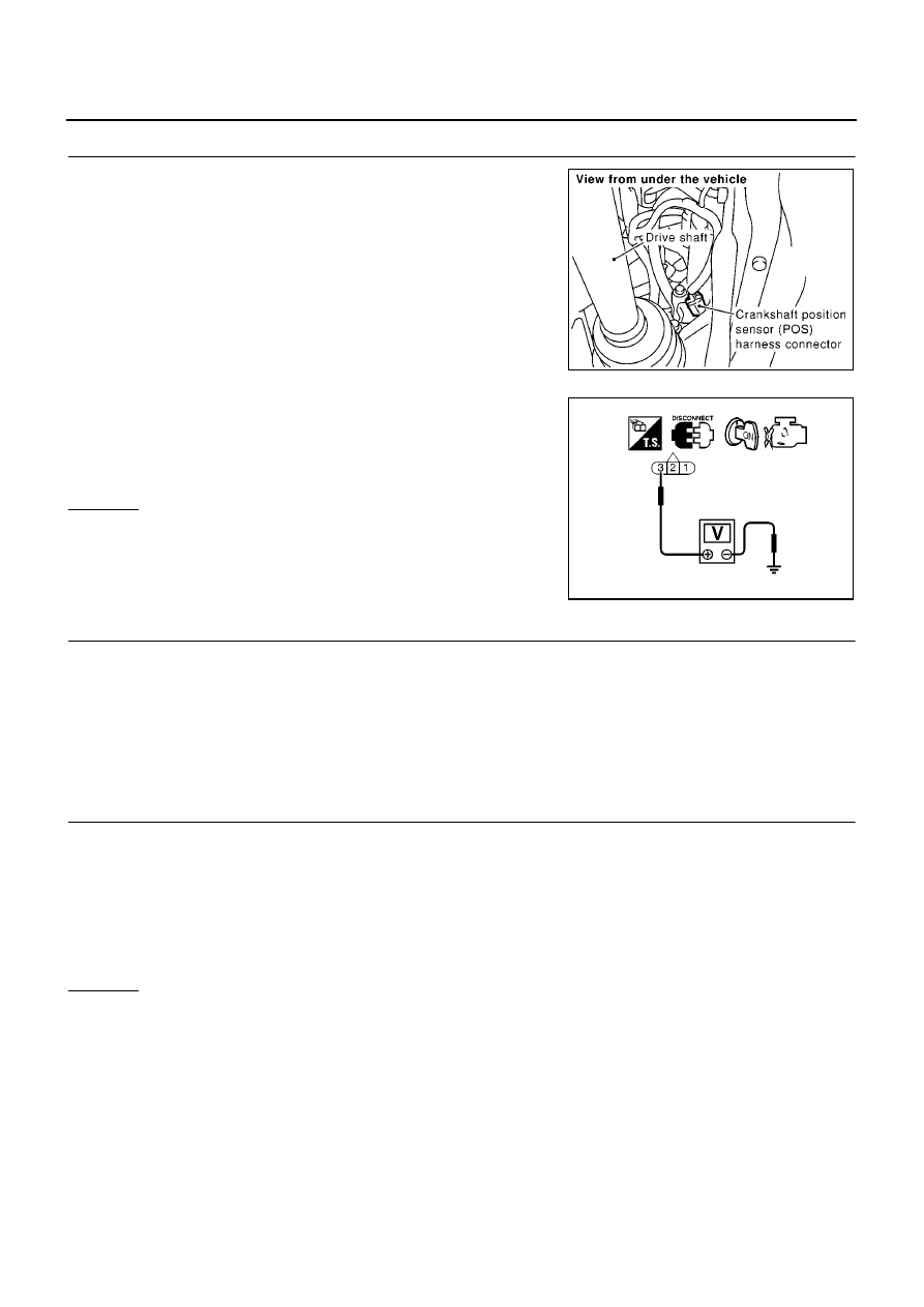
CHECK CKP SENSOR (POS) POWER SUPPLY CIRCUIT

1.

Disconnect crankshaft position (CKP) sensor (POS) harness
connector.

2.

Turn ignition switch “ON”.

3.

Check voltage between CKP sensor (POS) terminal 3 and
ground with CONSULT-II or tester.

4.

Also check harness for short to ground and short to power.

OK or NG

OK

>> GO TO 4.

NG

>> GO TO 3.

3.

DETECT MALFUNCTIONING PART

Check the following.

Harness connectors M71, F45

Harness for open or short between crankshaft position sensor (POS) and ECM

Harness for open or short between crankshaft position sensor (POS) and ECM relay

>> Repair open circuit or short to ground or short to power in harness or connectors.

4.

CHECK CKP SENSOR (POS) GROUND CIRCUIT FOR OPEN AND SHORT

1.

Turn ignition switch “OFF”.

2.

Disconnect ECM harness connector.

3.

Check harness continuity between ECM terminal 30 and CKP sensor (POS) terminal 1
Refer to Wiring Diagram.

4.

Also check harness for and short to ground and short to power.

OK or NG

OK

>> GO TO 5.

NG

>> Repair open circuit or short to ground or short to power in harness or connectors.

MBIB0103E

Voltage: Battery voltage

SEF509Y

Continuity should exist.

DTC P0335 CKP SENSOR (POS)

EC-743

[QG (WITHOUT EURO-OBD)]

C

D

E

F

G

H

I

J

K

L

M

A

EC

5.

CHECK CKP SENSOR (POS) INPUT SIGNAL CIRCUIT FOR OPEN AND SHORT

1.

Check harness continuity between ECM terminal 13 and CKP sensor (POS) terminal 2.
Refer to Wiring Diagram.

2.

Also check harness for short to ground and short to power.

OK or NG

OK

>> GO TO 6.

NG

>> Repair open circuit or short to ground or short to power in harness or connectors.

6.

CHECK CRANKSHAFT POSITION SENSOR (POS)

Refer to

EC-743, "Component Inspection"

.

OK or NG

OK

>> GO TO 7.

NG

>> Replace crankshaft position sensor (POS).

7.

CHECK GEAR TOOTH

Visually check for chipping signal plate gear tooth.

OK or NG

OK

>> GO TO 8.

NG

>> Replace the signal plate.

8.

CHECK INTERMITTENT INCIDENT

Refer to

EC-644, "TROUBLE DIAGNOSIS FOR INTERMITTENT INCIDENT"

.

>> INSPECTION END

Component Inspection

EBS00QYW

CRANKSHAFT POSITION SENSOR (POS)

1.

Loosen the fixing bolt of the sensor.

2.

Disconnect crankshaft position sensor (POS) harness connector.

3.

Remove the sensor.

4.

Visually check the sensor for chipping.

Continuity should exist.

PBIB0563E

EC-744

[QG (WITHOUT EURO-OBD)]

DTC P0335 CKP SENSOR (POS)

5.

Check resistance as shown in the figure.

6.

If NG, replace crankshaft position sensor (POS).

Removal and Installation

EBS00QYX

CRANKSHAFT POSITION SENSOR (POS)

Refer to

EM-74, "CYLINDER BLOCK"

.

Terminal No. (Polarity)

Resistance

[at 25

°

C (77

°

F)]

3 (+) - 1 (-)

Except 0 or

3 (+) - 2 (-)

2 (+) - 1 (-)

MBIB0024E

DTC P0340 CMP SENSOR (PHASE)

EC-745

[QG (WITHOUT EURO-OBD)]

C

D

E

F

G

H

I

J

K

L

M

A

EC

DTC P0340 CMP SENSOR (PHASE)

PFP:23731

Component Description

EBS00QYY

The camshaft position sensor (PHASE) senses the retraction of
intake valve camshaft to identify a particular cylinder. The camshaft
position sensor (PHASE) senses the piston position.
When the crankshaft position sensor (POS) system becomes inoper-
ative, the camshaft position sensor (PHASE) provides various con-
trols of engine parts instead, utilizing timing of cylinder identification
signals.
The sensor consists of a permanent magnet and Hall IC.
When engine is running, the high and low parts of the teeth cause
the gap with the sensor to change.
The changing gap causes the magnetic field near the sensor to
change.
Due to the changing magnetic field, the voltage from the sensor changes.

On Board Diagnosis Logic

EBS00QYZ

DTC Confirmation Procedure

EBS00QZ0

NOTE:
If “DTC Confirmation Procedure” has been previously conducted, always turn ignition switch “OFF” and wait at
least 10 seconds before conducting the next test.
TESTING CONDITION:
Before performing the following procedure, confirm that battery voltage is more than 10.5V with igni-
tion switch “ON”.

WITH CONSULT-II

1.

Turn ignition switch “ON”.

2.

Select “DATA MONITOR” mode with CONSULT-II.

3.

Crank engine for at least 2 seconds and run it for at least 5 sec-
onds at idle speed.

4.

If 1st trip DTC is detected, go to

EC-748, "Diagnostic Procedure"

.
If 1st trip DTC is not detected, go to next step.

5.

Maintain engine speed at more than 800 rpm for at least 5 sec-
onds.

6.

If 1st trip DTC is detected, go to

EC-748, "Diagnostic Procedure"

.

WITHOUT CONSULT-II

1.

Crank engine for at least 2 seconds and run it for at least 5 seconds at idle speed.

2.

Turn ignition switch “OFF”, wait at least 10 seconds and then turn “ON”.

3.

Perform “Diagnostic Test Mode II (Self-diagnostic results)” with ECM.

4.

If 1st trip DTC is detected, go to

EC-748, "Diagnostic Procedure"

.

If 1st trip DTC is not detected, go to next step.

5.

Turn ignition switch “OFF” and wait at least 10 seconds.

6.

Start engine and maintain engine speed at more than 800 rpm for at least 5 seconds.

PBIB0562E

DTC No.

Trouble diagnosis name

DTC detecting condition

Possible cause

P0340
0340

Camshaft position sensor
(PHASE) circuit

The cylinder No. signal is not sent to ECM
for the first few seconds during engine
cranking.

The cylinder No. signal is not set to ECM
during engine running.

The cylinder No. signal is not in the normal
pattern during engine running.

Harness or connectors
(The sensor circuit is open or shorted.)

Camshaft position sensor (PHASE)

Camshaft (Intake)

Starter motor (Refer to SC-13.)

Starting system circuit (Refer to SC-13.)

Dead (Weak) battery

SEF013Y


Content   ..  477  478  479  480   ..