Nissan Almera Tino V10. Manual - part 475


  Index      Nissan     Nissan Almera Tino V10 - Service Manual (2003 year)


Search            


Content   ..  473  474  475  476   ..


Nissan Almera Tino V10. Manual - part 475


EC-726

[QG (WITHOUT EURO-OBD)]

DTC P0226 APP SENSOR

2.

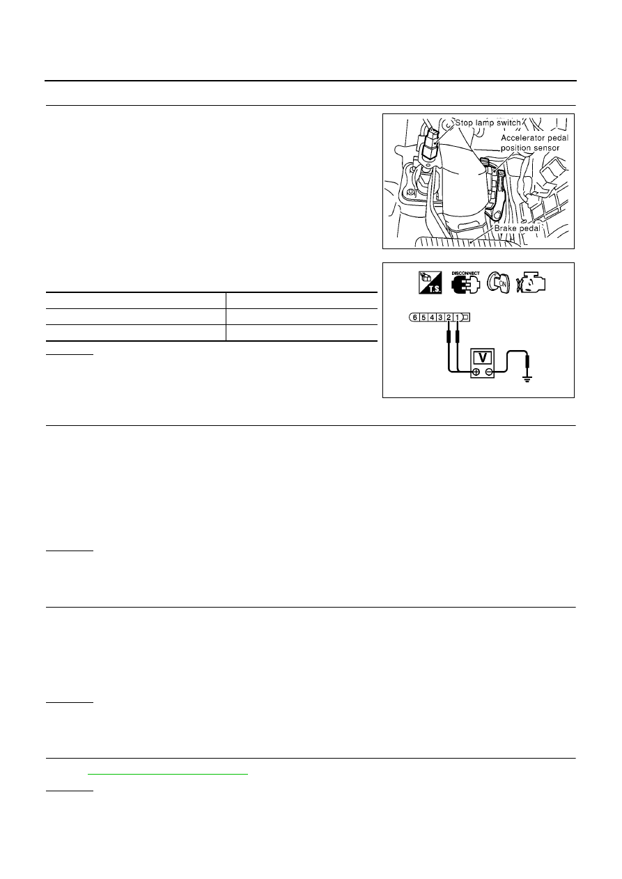
CHECK APP SENSOR POWER SUPPLY CIRCUIT

1.

Disconnect accelerator pedal position (APP) sensor harness
connector.

2.

Turn ignition switch “ON”.

3.

Check voltage between APP sensor terminals 1, 2 and ground
with CONSULT-II or tester.

OK or NG

OK

>> GO TO 3.

NG

>> Repair open circuit or short to ground or short to power

in harness or connectors.

3.

CHECK APP SENSOR GROUND CIRCUIT FOR OPEN AND SHORT

1.

Turn ignition switch “OFF”.

2.

Disconnect ECM harness connector.

3.

Check harness continuity between ECM terminal 82 and APP sensor terminal 4, ECM terminal 83 and
APP sensor terminal 5.
Refer to Wiring Diagram.

4.

Also check harness for short to ground and short to power.

OK or NG

OK

>> GO TO 4.

NG

>> Repair open circuit or short to ground or short to power in harness or connectors.

4.

CHECK APP SENSOR INPUT SIGNAL CIRCUIT FOR OPEN AND SHORT

1.

Check harness continuity between ECM terminal 106 and APP sensor terminal 3, ECM terminal 98 and
APP sensor terminal 6.
Refer to Wiring Diagram.

2.

Also check harness for short to ground and short to power.

OK or NG

OK

>> GO TO 5.

NG

>> Repair open circuit or short to ground or short to power in harness or connectors.

5.

CHECK APP SENSOR

Refer to

EC-727, "Component Inspection"

.

OK or NG

OK

>> GO TO 7.

NG

>> GO TO 6.

MBIB0152E

APP sensor terminal

Voltage (V)

1

Approximately 2.5

2

Approximately 5

PBIB0782E

Continuity should exist.

Continuity should exist.

DTC P0226 APP SENSOR

EC-727

[QG (WITHOUT EURO-OBD)]

C

D

E

F

G

H

I

J

K

L

M

A

EC

6.

REPLACE APP SENSOR

1.

Replace the accelerator pedal position sensor.

2.

Perform

EC-576, "Accelerator Pedal Released Position Learning"

.

3.

Perform

EC-576, "Throttle Valve Closed Position Learning"

.

4.

Perform

EC-576, "Idle Air Volume Learning"

.

>> INSPECTION END

7.

CHECK INTERMITTENT INCIDENT

Refer to

EC-644, "TROUBLE DIAGNOSIS FOR INTERMITTENT INCIDENT"

.

>> INSPECTION END

Component Inspection

EBS00QY9

ACCELERATOR PEDAL POSITION SENSOR

1.

Reconnect all harness connectors disconnected.

2.

Turn ignition switch “ON”.

3.

Check voltage between ECM terminals 106 (APP sensor 1 sig-
nal), 98 (APP sensor 2 signal) and engine ground under the fol-
lowing conditions.

4.

If NG, replace accelerator pedal assembly and go to the next
step.

5.

Perform

EC-576, "Accelerator Pedal Released Position Learning"

.

6.

Perform

EC-576, "Throttle Valve Closed Position Learning"

.

7.

Perform

EC-576, "Idle Air Volume Learning"

.

Remove and Installation

EBS00QYA

ACCELERATOR PEDAL

Refer to “ACCELERATOR CONTROL SYSTEM”, FE-3.

Terminal

Accelerator pedal

Voltage

106

(Accelerator pedal position

sensor 1)

Fully released

0.35 - 0.67V

Fully depressed

More than 3.9V

98
(Accelerator pedal position
sensor 2)

Fully released

0.17 - 0.34V

Fully depressed

More than 1.95V

MBIB0023E

EC-728

[QG (WITHOUT EURO-OBD)]

DTC P0227, P0228 APP SENSOR

DTC P0227, P0228 APP SENSOR

PFP:18002

Component Description

EBS00QYB

The accelerator pedal position sensor is installed on the upper end
of the accelerator pedal assembly. The sensor detects the accelera-
tor position and sends a signal to the ECM.
Accelerator pedal position sensor has two sensors. These sensors
are a kind of potentiometers which transform the accelerator pedal
position into output voltage, and emit the voltage signal to the ECM.
In addition, these sensors detect the opening and closing speed of
the accelerator pedal and feed the voltage signals to the ECM. The
ECM judges the current opening angle of the accelerator pedal from
these signals and controls the throttle control motor based on these
signals.
Idle position of the accelerator pedal is determined by the ECM
receiving the signal from the accelerator pedal position sensor. The ECM uses this signal for the engine oper-
ation such as fuel cut.

CONSULT-II Reference Value in Data Monitor Mode

EBS00QYC

Specification data are reference values.

*: Accelerator pedal position sensor 2 signal is converted by ECM internally. Thus, it differs from ECM terminal voltage signal.

On Board Diagnosis Logic

EBS00QYD

These self-diagnoses have the one trip detection logic.

FAIL-SAFE MODE

When the malfunction is detected, the ECM enters fail-safe mode and the MI lights up.

DTC Confirmation Procedure

EBS00QYE

NOTE:
If “DTC Confirmation Procedure” has been previously conducted, always turn ignition switch “OFF” and wait at
least 10 seconds before conducting the next test.
TESTING CONDITION:
Before performing the following procedure, confirm that battery voltage is more than 10V at idle.

PBIB0146E

MONITOR ITEM

CONDITION

SPECIFICATION

ACCEL SEN1
ACCEL SEN2*

Ignition switch: ON
(engine stopped)

Accelerator pedal: Fully released

0.35 - 0.67V

Accelerator pedal: Fully depressed

More than 3.9V

CLSD THL POS

Ignition switch: ON

Accelerator pedal: Fully released

ON

Accelerator pedal: Slightly depressed

OFF

DTC No.

Trouble diagnosis name

DTC detecting condition

Possible cause

P0227
0227

Accelerator pedal position
sensor 1 circuit low input

An excessively low voltage from the APP sensor 1
is sent to ECM.

Harness or connectors
(The APP sensor 1 circuit is open or
shorted.)

Accelerator pedal position sensor
(Accelerator pedal position sensor 1)

P0228
0228

Accelerator pedal position
sensor 1 circuit high input

An excessively high voltage from the APP sensor 1
is sent to ECM.

Engine operating condition in fail-safe mode

The ECM controls the electric throttle control actuator in regulating the throttle opening in order for the idle position to be within +10
degrees.
The ECM regulates the opening speed of throttle valve to be slower than the normal condition.
So, the acceleration will be poor.

DTC P0227, P0228 APP SENSOR

EC-729

[QG (WITHOUT EURO-OBD)]

C

D

E

F

G

H

I

J

K

L

M

A

EC

WITH CONSULT-II

1.

Turn ignition switch “ON”.

2.

Select “DATA MONITOR” mode with CONSULT-II.

3.

Start engine and let it idle for 1 second.

4.

If DTC is detected, go to

EC-731, "Diagnostic Procedure"

.

WITHOUT CONSULT-II

1.

Start engine and let it idle for 1 second.

2.

Turn ignition switch “OFF”, wait at least 10 seconds and then turn “ON”.

3.

Perform “Diagnostic Test Mode II (Self-diagnostic results)” with ECM.

4.

If DTC is detected, go to

EC-731, "Diagnostic Procedure"

.

SEF058Y


Content   ..  473  474  475  476   ..