Nissan Almera Tino V10. Manual - part 474
EC-722
[QG (WITHOUT EURO-OBD)]
DTC P0226 APP SENSOR
DTC P0226 APP SENSOR
PFP:18002
Component Description
EBS00QY3
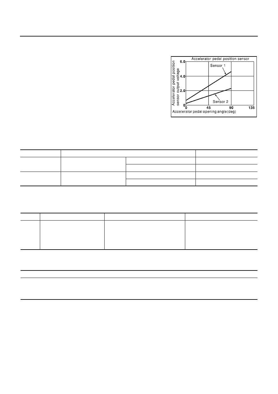
The accelerator pedal position sensor is installed on the upper end
of the accelerator pedal assembly. The sensor detects the accelera-
tor position and sends a signal to the ECM.
Accelerator pedal position sensor has two sensors. These sensors
are a kind of potentiometers which transform the accelerator pedal
position into output voltage, and emit the voltage signal to the ECM.
In addition, these sensors detect the opening and closing speed of
the accelerator pedal and feed the voltage signals to the ECM. The
ECM judges the current opening angle of the accelerator pedal from
these signals and controls the throttle control motor based on these
signals.
Idle position of the accelerator pedal is determined by the ECM
receiving the signal from the accelerator pedal position sensor. The ECM uses this signal for the engine oper-
ation such as fuel cut.
CONSULT-II Reference Value in Data Monitor Mode
EBS00QY4
Specification data are reference values.
*: Accelerator pedal position sensor 2 signal is converted by ECM internally. Thus, it differs from ECM terminal voltage signal.
On Board Diagnosis Logic
EBS00QY5
This self-diagnosis has the one trip detection logic.
FAIL-SAFE MODE
When the malfunction is detected, the ECM enters fail-safe mode and the MI lights up.
DTC Confirmation Procedure
EBS00QY6
NOTE:
If “DTC Confirmation Procedure” has been previously conducted, always turn ignition switch “OFF” and wait at
least 10 seconds before conducting the next test.
TESTING CONDITION:
Before performing the following procedure, confirm that battery voltage is more than 10V at idle.
PBIB0146E
MONITOR ITEM
CONDITION
SPECIFICATION
ACCEL SEN1
ACCEL SEN2*
●
Ignition switch: ON
(engine stopped)
Accelerator pedal: Fully released
0.35 - 0.67V
Accelerator pedal: Fully depressed
More than 3.9V
CLSD THL POS
●
Ignition switch: ON
Accelerator pedal: Fully released
ON
Accelerator pedal: Slightly depressed
OFF
DTC No.
Trouble diagnosis name
DTC detecting condition
Possible cause
P0226
0226
Accelerator pedal position sensor
circuit range/performance problem
Rationally incorrect voltage is sent to ECM
compared with the signals from APP sensor
1 and APP sensor 2.
●
Harness or connector
(The APP sensor 1 and 2 circuit is
open or shorted.)
●
Accelerator pedal position sensor 1
and 2
Engine operating condition in fail-safe mode
The ECM controls the electric throttle control actuator in regulating the throttle opening in order for the idle position to be within +10
degrees.
The ECM regulates the opening speed of throttle valve to be slower than the normal condition.
So, the acceleration will be poor.