Nissan Almera Tino V10. Manual - part 450


  Index      Nissan     Nissan Almera Tino V10 - Service Manual (2003 year)


Search            


Content   ..  448  449  450  451   ..


Nissan Almera Tino V10. Manual - part 450


EC-626

[QG (WITHOUT EURO-OBD)]

TROUBLE DIAGNOSIS

2.

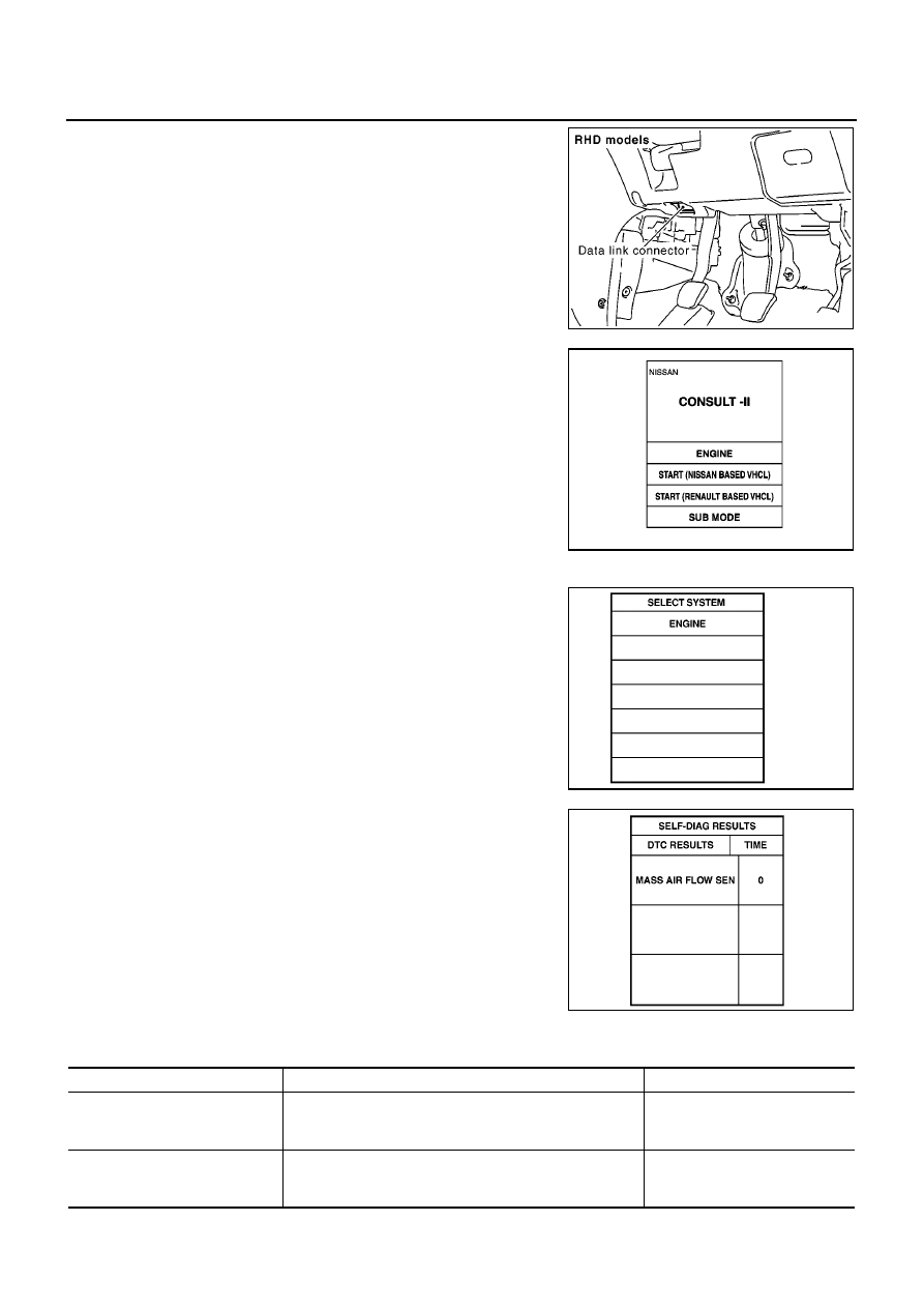
Connect “CONSULT-II” and “CONSULT-II CONVERTER” to
data link connector, which is located under the driver’s side dash
panel.

3.

Turn ignition switch ON.

4.

Touch “START (NISSAN BASED VHCL)”.

5.

Touch “ENGINE”.
If “ENGIEN” is not indicated, go to “CONSULT-II Data Link Con-
nector (DLC) Circuit”, GI-37.

6.

Perform each diagnostic test mode according to each service
procedure.

For further information, see the CONSULT-II Operation Manual.

WORK SUPPORT MODE
Work Item

MBIB1000E

MBIB0233E

SEF995X

SEC767D

WORK ITEM

CONDITION

USAGE

FUEL PRESSURE RELEASE

FUEL PUMP WILL STOP BY TOUCHING “START” DUR-
ING IDLING.
CRANK A FEW TIMES AFTER ENGINE STALLS.

When releasing fuel pressure
from fuel line

IDLE AIR VOL LEARN

THE IDLE AIR VOLUME THAT KEEPS THE ENGINE
WITHIN THE SPECIFIED RANGE IS MEMORIZED IN
ECM.

When learning the idle air volume

TROUBLE DIAGNOSIS

EC-627

[QG (WITHOUT EURO-OBD)]

C

D

E

F

G

H

I

J

K

L

M

A

EC

*: This function is not necessary in the usual service procedure.

SELF-DIAG RESULTS MODE
Self Diagnostic Item

Regarding items of “DTC and 1st trip DTC”, refer to

EC-554, "INDEX FOR DTC"

.)

Freeze Frame Data and 1st Trip Freeze Frame Data

*1: The items are the same as those of 1st trip freeze frame data.
*2: A/T models.

SELF-LEARNING CONT

THE COEFFICIENT OF SELF-LEARNING CONTROL
MIXTURE RATIO RETURNS TO THE ORIGINAL COEF-
FICIENT.

When clearing the coefficient of
self-learning control value

TARGET IDLE RPM ADJ

*

IDLE CONDITION

When setting target idle speed

TARGET IGN TIM ADJ

*

IDLE CONDITION

When adjusting target ignition tim-
ing

WORK ITEM

CONDITION

USAGE

Freeze frame data

item

*1

Description

DIAG TROUBLE
CODE
[PXXXX]

The engine control component part/control system has a trouble code, it is displayed as “PXXXX”. (Refer
to

EC-554, "INDEX FOR DTC"

.)

FUEL SYS-B1

“Fuel injection system status” at the moment a malfunction is detected is displayed.

One mode in the following is displayed.
“MODE 2”: Open loop due to detected system malfunction
“MODE 3”: Open loop due to driving conditions (power enrichment, deceleration enrichment)
“MODE 4”: Closed loop - using oxygen sensor(s) as feedback for fuel control
“MODE 5”: Open loop - has not yet satisfied condition to go to closed loop

FUEL SYS-B2

*2

CAL/LD VALUE [%]

The calculated load value at the moment a malfunction is detected is displayed.

COOLANT TEMP [

°

C]

or [

°

F]

The engine coolant temperature at the moment a malfunction is detected is displayed.

L-FUEL TRIM-B1 [%]

“Long-term fuel trim” at the moment a malfunction is detected is displayed.

The long-term fuel trim indicates much more gradual feedback compensation to the base fuel schedule
than short-term fuel trim.

S-FUEL TRIM-B1 [%]

“Short-term fuel trim” at the moment a malfunction is detected is displayed.

The short-term fuel trim indicates dynamic or instantaneous feedback compensation to the base fuel
schedule.

ENGINE SPEED
[rpm]

The engine speed at the moment a malfunction is detected is displayed.

VEHICL SPEED [km/
h] or [mph]

The vehicle speed at the moment a malfunction is detected is displayed.

B/FUEL SCHDL
[msec]

The base fuel schedule at the moment a malfunction is detected is displayed.

INT/A TEMP SE [

°

C]

or [

°

F]

The intake air temperature at the moment a malfunction is detected is displayed.

EC-628

[QG (WITHOUT EURO-OBD)]

TROUBLE DIAGNOSIS

DATA MONITOR MODE
Monitored Item

×

: Applicable

Monitored item

[Unit]

ECM

INPUT

SIG-

NALS

MAIN

SIG-

NALS

CAN

DIAG
SUP-

PORT

MNTR

Description

Remarks

ENG SPEED [rpm]

×

×

Indicates the engine speed computed
from the signals of the crankshaft posi-
tion sensor (POS) and camshaft posi-
tion sensor (PHASE).

Accuracy becomes poor if engine
speed drops below the idle rpm.

If the signal is interrupted while the
engine is running, an abnormal
value may be indicated.

MAS A/F SE-B1 [V]

×

×

The signal voltage of the mass air flow
sensor is displayed.

When the engine is stopped, a
certain value is indicated.

B/FUEL SCHDL
[msec]

×

“Base fuel schedule” indicates the fuel
injection pulse width programmed into
ECM, prior to any learned on board cor-
rection.

A/F ALPHA-B1 [%]

×

The mean value of the air-fuel ratio
feedback correction factor per cycle is
indicated.

When the engine is stopped, a
certain value is indicated.

This data also includes the data
for the air-fuel ratio learning con-
trol.

A/F ALPHA-B2 [%]

*

×

COOLAN TEMP/S
[

°

C] or [

°

F]

×

×

The engine coolant temperature (deter-
mined by the signal voltage of the
engine coolant temperature sensor) is
displayed.

When the engine coolant tempera-
ture sensor is open or short-cir-
cuit, ECM enters fail-safe mode.
The engine coolant temperature
determined by the ECM is dis-
played.

HO2S1 (B1) [V]

×

×

The signal voltage of the heated oxygen
sensor 1 is displayed.

HO2S1 (B2) [V]

*

×

HO2S2 (B1) [V]

×

×

The signal voltage of the heated oxygen
sensor 2 is displayed.

HO2S2 (B2) [V]

*

×

HO2S1 MNTR (B1)
[RICH/LEAN]

×

×

Display of heated oxygen sensor 1 sig-
nal during air-fuel ratio feedback control:
RICH ... means the mixture became
“rich”, and control is being affected
toward a leaner mixture.
LEAN ... means the mixture became
“lean”, and control is being affected
toward a rich mixture.

After turning ON the ignition
switch, “RICH” is displayed until
air-fuel mixture ratio feedback
control begins.

When the air-fuel ratio feedback is
clamped, the value just before the
clamping is displayed continu-
ously.

HO2S1 MNTR (B2)

[RICH/LEAN]

*

×

HO2S2 MNTR (B1)
[RICH/LEAN]

×

Display of heated oxygen sensor 2 sig-
nal:
RICH ... means the amount of oxygen
after three way catalyst is relatively
small.
LEAN ... means the amount of oxygen
after three way catalyst is relatively
large.

When the engine is stopped, a
certain value is indicated.

HO2S2 MNTR (B2)

[RICH/LEAN]

*

×

VHCL SPEED SE
[km/h] or [mph]

×

×

The vehicle speed computed from the
vehicle speed signal sent from combina-
tion meter is displayed.

BATTERY VOLT
[V]

×

×

The power supply voltage of ECM is dis-
played.

TROUBLE DIAGNOSIS

EC-629

[QG (WITHOUT EURO-OBD)]

C

D

E

F

G

H

I

J

K

L

M

A

EC

ACCEL SEN 1 [V]

×

×

The accelerator pedal position sensor
signal voltage is displayed.

ACCEL SEN 2 [V]

×

THRTL SEN 1 [V]

×

×

The throttle position sensor signal volt-
age is displayed.

THRTL SEN 2 [V]

×

INT/A TEMP SE
[

°

C] or [

°

F]

×

×

The intake air temperature (determined
by the signal voltage of the intake air
temperature sensor) is indicated.

START SIGNAL
[ON/OFF]

×

×

Indicates [ON/OFF] condition of the
starter signal computed from the signals
of the crankshaft position sensor (POS),
camshaft position sensor (PHASE) and
battery voltage.

After starting the engine, [OFF] is
displayed regardless of the starter
signal.

CLSD THL POS
[ON/OFF]

×

×

Indicates idle position [ON/OFF] com-
puted by ECM according to the acceler-
ator pedal position sensor signal.

AIR COND SIG
[ON/OFF]

×

×

Indicates [ON/OFF] condition of the air
conditioner switch as determined by the
air conditioner signal.

P/N POSI SW
[ON/OFF]

×

×

Indicates [ON/OFF] condition from the
park/neutral position (PNP) switch sig-
nal.

PW/ST SIGNAL
[ON/OFF]

×

×

[ON/OFF] condition of the power steer-
ing oil pressure switch as determined by
the power steering oil pressure signal is
indicated.

LOAD SIGNAL
[ON/OFF]

×

×

Indicates [ON/OFF] condition from the
electrical load signal.
ON ... Rear window defogger switch is
ON and/or lighting switch is in 2nd posi-
tion.
OFF ... Both rear window defogger
switch and lighting switch are OFF.

IGNITION SW

[ON/OFF]

×

Indicates [ON/OFF] condition from igni-
tion switch.

HEATER FAN SW
[ON/OFF]

×

Indicates [ON/OFF] condition from the
heater fan switch signal.

BRAKE SW

[ON/OFF]

×

Indicates [ON/OFF] condition from the
stop lamp switch signal.

INJ PULSE-B1
[msec]

×

Indicates the actual fuel injection pulse
width compensated by ECM according
to the input signals.

When the engine is stopped, a
certain computed value is indi-
cated.

INJ PULSE-B2

[msec]

*

IGN TIMING
[BTDC]

×

Indicates the ignition timing computed
by ECM according to the input signals.

When the engine is stopped, a
certain value is indicated.

PURG VOL C/V
[%]

Indicates the EVAP canister purge vol-
ume control solenoid valve control value
computed by the ECM according to the
input signals.

The opening becomes larger as the
value increases.

Monitored item

[Unit]

ECM

INPUT

SIG-

NALS

MAIN

SIG-

NALS

CAN

DIAG
SUP-

PORT

MNTR

Description

Remarks


Content   ..  448  449  450  451   ..