Nissan Almera Tino V10. Manual - part 449
EC-622
[QG (WITHOUT EURO-OBD)]
TROUBLE DIAGNOSIS
62
Y/R
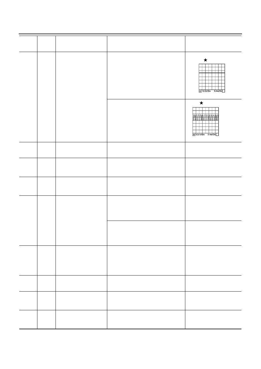
Intake valve timing control
solenoid valve
[Engine is running]
●
Warm-up condition
●
Idle speed
BATTERY VOLTAGE
(11 - 14V)
[Engine is running]
●
Warm-up condition
●
When revving engine up to 2,000 rpm
quickly
7 - 10V
65
G
Sensor power supply
(Power steering pressure
sensor)
[Ignition switch “ON”]
Approximately 5V
66
B
Sensor ground
(Throttle position sensor)
[Engine is running]
●
Warm-up condition
●
Idle speed
Approximately 0V
67
B
Sensor ground
(Mass air flow sensor)
[Engine is running]
●
Warm-up condition
●
Idle speed
Approximately 0V
68
R
Throttle position sensor 2
[Ignition switch “ON”]
●
Engine stopped
●
Shift lever position is “D”
●
Accelerator pedal fully released
Less than 4.75V
[Ignition switch “ON”]
●
Engine stopped
●
Shift lever position is “D”
●
Accelerator pedal fully depressed
More than 0.36V
69
L
Refrigerant pressure sensor
[Engine is running]
●
Warm-up condition
●
Both A/C switch and blower switch are
“ON”
(Compressor operates.)
1.0 - 4.0V
72
BR/W
Engine coolant temperature
sensor
[Engine is running]
Approximately 0 - 4.8V
Output voltage varies with
engine coolant temperature.
73
B
Sensor ground
(Engine coolant temperature
sensor)
[Engine is running]
●
Warm-up condition
●
Idle speed
Approximately 0V
74
B
Sensors' ground
(Heated oxygen sensor)
[Engine is running]
●
Warm-up condition
●
Idle speed
Approximately 0V
TERMI-
NAL
NO.
WIRE
COLOR
ITEM
CONDITION
DATA (DC Voltage)
MBIB0052E
PBIB0532E