Nissan Almera Tino V10. Manual - part 427
EC-534
[QG (WITH EURO-OBD)]
FUEL PUMP CIRCUIT
8.
CHECK FUEL PUMP RELAY
Refer to
EC-534, "Component Inspection"
.
OK or NG
OK
>> GO TO 9.
NG
>> Replace fuel pump relay.
9.
CHECK FUEL PUMP
Refer to
EC-534, "Component Inspection"
.
OK or NG
OK
>> GO TO 10.
NG
>> Replace fuel pump.
10.
CHECK INTERMITTENT INCIDENT
Refer to
EC-138, "TROUBLE DIAGNOSIS FOR INTERMITTENT INCIDENT"
.
>> INSPECTION END
Component Inspection
EBS00QTM
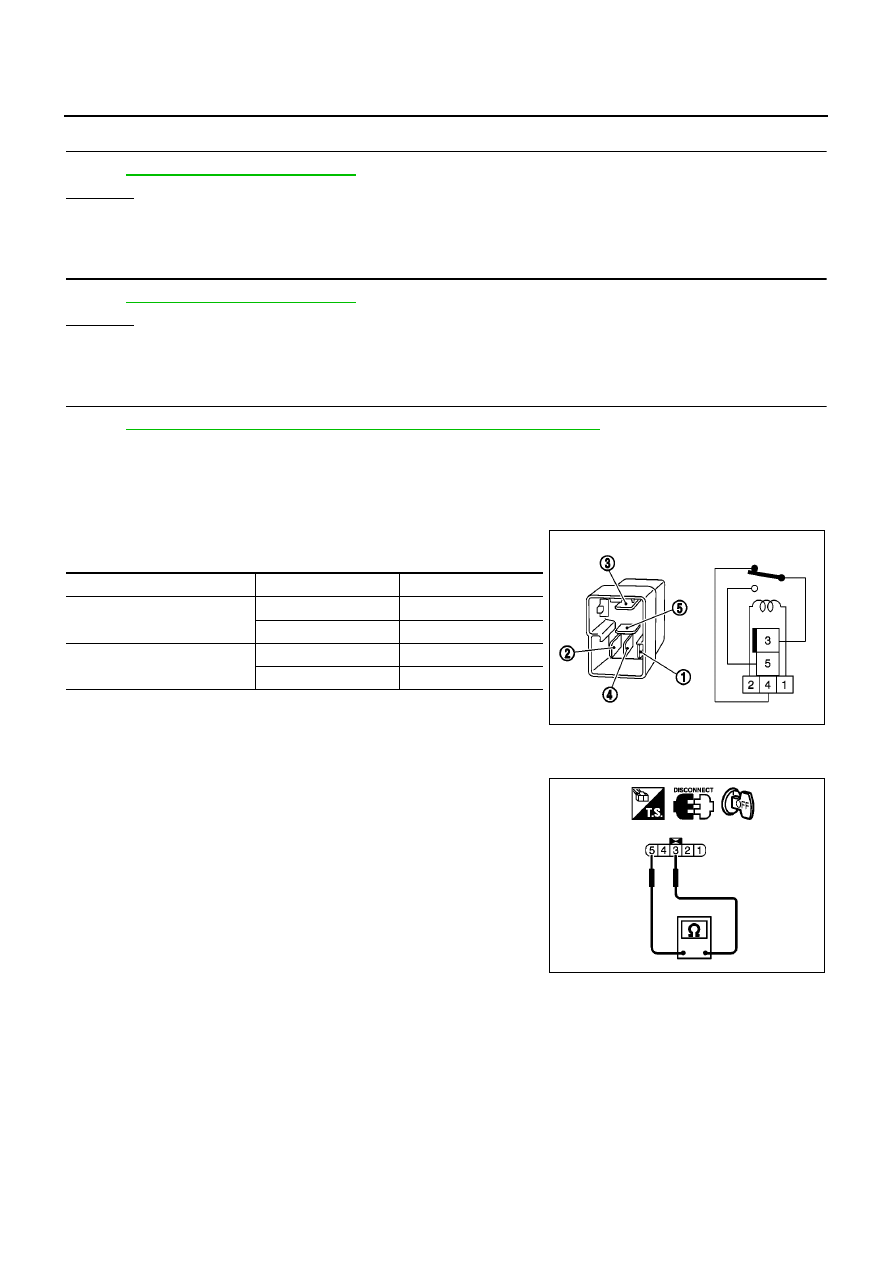
FUEL PUMP RELAY
Check continuity between terminals 3 and 4, 3 and 5 under the fol-
lowing conditions.
FUEL PUMP
1.
Disconnect fuel level sensor unit and fuel pump harness connector.
2.
Check resistance between fuel level sensor unit and fuel pump
terminals 3 and 5.
Removal and Installation
EBS00QTN
FUEL PUMP
Refer to “Fuel Pump, Fuel Level Sensor Unit and Fuel Filter”, FE-9.
Conditions
Terminals
Continuity
12V direct current supply
between terminals 1 and 2
3 and 4
No
3 and 5
Yes
No current supply
3 and 4
Yes
3 and 5
No
MBIB0056E
Resistance: Approximately 1.0
Ω
[at 25
°
C (77
°
F)]
PBIB0658E