Index Nissan Nissan Almera Tino V10 - Service Manual (2003 year)
Search
Content .. 418 419 420 421 ..
Nissan Almera Tino V10. Manual - part 420
EC-506
[QG (WITH EURO-OBD)]
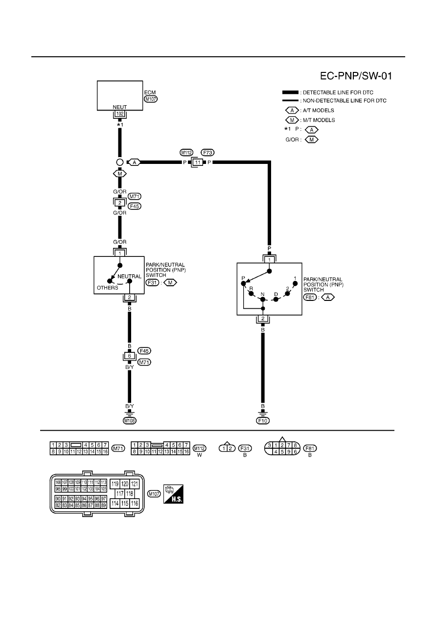
DTC P1706 PNP SWITCH
Wiring Diagram
EBS00QSY
YEC470A