Nissan Almera Tino V10. Manual - part 400
EC-426
[QG (WITH EURO-OBD)]
DTC P1144 HO2S1 (M/T MODELS)
●
Before installing new oxygen sensor, clean exhaust system threads using Oxygen Sensor Thread
Cleaner tool J-43897-18 or J-43897-12 and approved anti-seize lubricant.
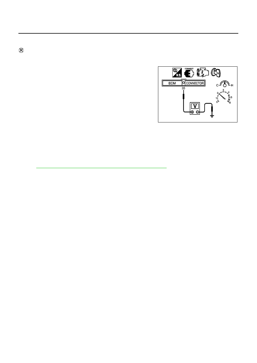
Without CONSULT-II
1.
Start engine and warm it up to normal operating temperature.
2.
Set voltmeter probes between ECM terminal 35 (HO2S1 signal) and engine ground.
3.
Check the following with engine speed held at 2,000 rpm con-
stant under no load.
●
The voltage fluctuates between 0 to 0.3V and 0.6 to 1.0V
more than 5 times within 10 seconds.
●
The maximum voltage is over 0.6V at least one time.
●
The minimum voltage is below 0.3V at least one time.
●
The voltage never exceeds 1.0V.
1 time: 0 - 0.3V
→
0.6 - 1.0V
→
0 - 0.3V
2 times: 0 - 0.3V
→
0.6 - 1.0V
→
0 - 0.3V
→
0.6 - 1.0V
CAUTION:
●
Discard any heated oxygen sensor which has been dropped
from a height of more than 0.5 m (19.7 in) onto a hard surface such as a concrete floor; use a new
one.
●
Before installing new oxygen sensor, clean exhaust system threads using Oxygen Sensor Thread
Cleaner tool J-43897-18 or J-43897-12 and approved anti-seize lubricant.
Removal and Installation
EBS00QQA
HEATED OXYGEN SENSOR 1
Refer to
EM-21, "EXHAUST MANIFOLD AND CATALYTIC CONVERTER"
.
MBIB0018E