Nissan Almera Tino V10. Manual - part 398


  Index      Nissan     Nissan Almera Tino V10 - Service Manual (2003 year)


Search            


Content   ..  396  397  398  399   ..


Nissan Almera Tino V10. Manual - part 398


EC-418

[QG (WITH EURO-OBD)]

DTC P1143, P1163 HO2S1 (A/T MODELS)

3.

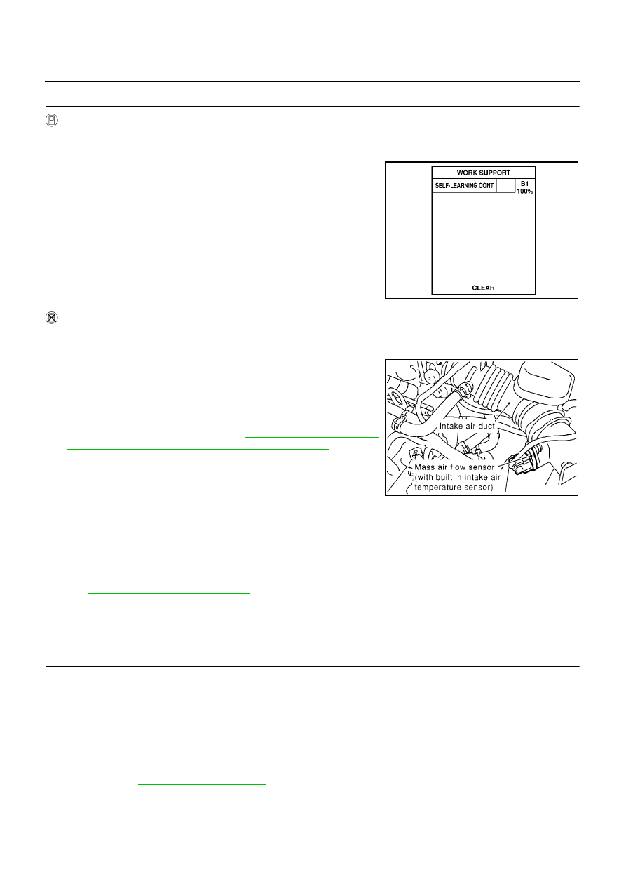
CLEAR THE SELF-LEARNING DATA

With CONSULT-II

1.

Start engine and warm it up to normal operating temperature.

2.

Select “SELF-LEARNING CONT” in “WORK SUPPORT” mode with CONSULT-II.

3.

Clear the self-learning control coefficient by touching “CLEAR”.

4.

Run engine for at least 10 minutes at idle speed.
Is the 1st trip DTC P0171 or P0174 detected?
Is it difficult to start engine?

Without CONSULT-II

1.

Start engine and warm it up to normal operating temperature.

2.

Turn ignition switch “OFF”.

3.

Disconnect mass air flow sensor harness connector, and restart
and run engine for at least 5 seconds at idle speed.

4.

Stop engine and reconnect mass air flow sensor harness con-
nector.

5.

Make sure that DTC P0102 is displayed.

6.

Erase the DTC memory. Refer to

EC-68, "HOW TO ERASE

EMISSION-RELATED DIAGNOSTIC INFORMATION"

.

7.

Make sure that DTC P0000 is displayed.

8.

Run engine for at least 10 minutes at idle speed.
Is the 1st trip DTC P0171 or P0174 detected?
Is it difficult to start engine?

Yes or No

Yes

>> Perform trouble diagnosis for DTC P0171, P0174. Refer to

EC-288

.

No

>> GO TO 4.

4.

CHECK HEATED OXYGEN SENSOR 1 HEATER

Refer to

EC-164, "Component Inspection"

.

OK or NG

OK

>> GO TO 5.

NG

>> Replace malfunctioning heated oxygen sensor 1.

5.

CHECK HEATED OXYGEN SENSOR 1

Refer to

EC-419, "Component Inspection"

.

OK or NG

OK

>> GO TO 6.

NG

>> Replace malfunctioning heated oxygen sensor 1.

6.

CHECK INTERMITTENT INCIDENT

Refer to

EC-138, "TROUBLE DIAGNOSIS FOR INTERMITTENT INCIDENT"

.

For circuit, refer to

EC-201, "Wiring Diagram"

.

>> INSPECTION END

SEF215Z

MBIB0096E

DTC P1143, P1163 HO2S1 (A/T MODELS)

EC-419

[QG (WITH EURO-OBD)]

C

D

E

F

G

H

I

J

K

L

M

A

EC

Component Inspection

EBS00QQ1

HEATED OXYGEN SENSOR 1

With CONSULT-II

1.

Start engine and warm it up to normal operating temperature.

2.

Select “MANU TRIG” and adjust “TRIGGER POINT” to 100% in “DATA MONITOR” mode with CONSULT-
II.

3.

Select “HO2S1 (B1)/(B2)” and “HO2S1 MNTR (B1)/(B2)”.

4.

Hold engine speed at 2,000 rpm under no load during the following steps.

5.

Touch “RECORD” on CONSULT-II screen.

6.

Check the following.

“HO2S1 MNTR (B1)/(B2)” in “DATA MONITOR” mode
changes from “RICH” to “LEAN” to “RICH” more than 5 times
in 10 seconds.
5 times (cycles) are counted as shown at right.

“HO2S1 (B1)/(B2)” voltage goes above 0.6V at least once.

“HO2S1 (B1)/(B2)” voltage goes below 0.3V at least once.

“HO2S1 (B1)/(B2)” voltage never exceeds 1.0V.

CAUTION:

Discard any heated oxygen sensor which has been dropped from a height of more than 0.5 m (19.7
in) onto a hard surface such as a concrete floor; use a new one.

Before installing new oxygen sensor, clean exhaust system threads using Oxygen Sensor Thread
Cleaner tool J-43897-18 or J-43897-12 and approved anti-seize lubricant.

SEF646Y

SEF647Y

SEF648Y

EC-420

[QG (WITH EURO-OBD)]

DTC P1143, P1163 HO2S1 (A/T MODELS)

Without CONSULT-II

1.

Start engine and warm it up to normal operating temperature.

2.

Set voltmeter probes between ECM terminal 35 [HO2S1 (B1) signal] or 36 [HO2S1 (B2) signal] and
engine ground.

3.

Check the following with engine speed held at 2,000 rpm con-
stant under no load.

The voltage fluctuates between 0 to 0.3V and 0.6 to 1.0V
more than 5 times within 10 seconds.

The maximum voltage is over 0.6V at least one time.

The minimum voltage is below 0.3V at least one time.

The voltage never exceeds 1.0V.

1 time: 0 - 0.3V

0.6 - 1.0V

0 - 0.3V

2 times: 0 - 0.3V

0.6 - 1.0V

0 - 0.3V

0.6 - 1.0V

CAUTION:

Discard any heated oxygen sensor which has been dropped
from a height of more than 0.5 m (19.7 in) onto a hard surface such as a concrete floor; use a new
one.

Before installing new oxygen sensor, clean exhaust system threads using Oxygen Sensor Thread
Cleaner tool J-43897-18 or J-43897-12 and approved anti-seize lubricant.

Removal and Installation

EBS00QQ2

HEATED OXYGEN SENSOR 1

Refer to

EM-21, "EXHAUST MANIFOLD AND CATALYTIC CONVERTER"

.

MBIB0019E

DTC P1144 HO2S1 (M/T MODELS)

EC-421

[QG (WITH EURO-OBD)]

C

D

E

F

G

H

I

J

K

L

M

A

EC

DTC P1144 HO2S1 (M/T MODELS)

PFP:22690

Component Description

EBS00QQ3

The heated oxygen sensor 1 is placed into the exhaust manifold. It
detects the amount of oxygen in the exhaust gas compared to the
outside air. The heated oxygen sensor 1 has a closed-end tube
made of ceramic zirconia. The zirconia generates voltage from
approximately 1V in richer conditions to 0V in leaner conditions. The
heated oxygen sensor 1 signal is sent to the ECM. The ECM adjusts
the injection pulse duration to achieve the ideal air-fuel ratio. The
ideal air-fuel ratio occurs near the radical change from 1V to 0V.

CONSULT-II Reference Value in Data Monitor Mode

EBS00QQ4

Specification data are reference values.

On Board Diagnosis Logic

EBS00QQ5

To judge the malfunction, the output from the heated oxygen sensor
1 is monitored to determine whether the “rich” output is sufficiently
high and “lean” output is sufficiently low. When both the outputs are
shifting to the rich side, the malfunction will be detected.

SEF463R

SEF288D

MONITOR ITEM

CONDITION

SPECIFICATION

HO2S1 (B1)

Engine: After warming up

Maintaining engine speed at 2,000
rpm

0 - 0.3V

←→

Approx. 0.6 - 1.0V

HO2S1 MNTR (B1)

LEAN

←→

RICH

Changes more than 5 times dur-
ing 10 seconds.

SEF299U

DTC No.

Trouble diagnosis name

DTC detecting condition

Possible cause

P1144
1144

Heated oxygen sensor 1
rich shift monitoring

The maximum and minimum voltages from the
sensor are beyond the specified voltages.

Heated oxygen sensor 1

Heated oxygen sensor 1 heater

Fuel pressure

Injectors


Content   ..  396  397  398  399   ..