Nissan Almera Tino V10. Manual - part 392


  Index      Nissan     Nissan Almera Tino V10 - Service Manual (2003 year)


Search            


Content   ..  390  391  392  393   ..


Nissan Almera Tino V10. Manual - part 392


EC-394

[QG (WITH EURO-OBD)]

DTC P1122 ELECTRIC THROTTLE CONTROL FUNCTION

2.

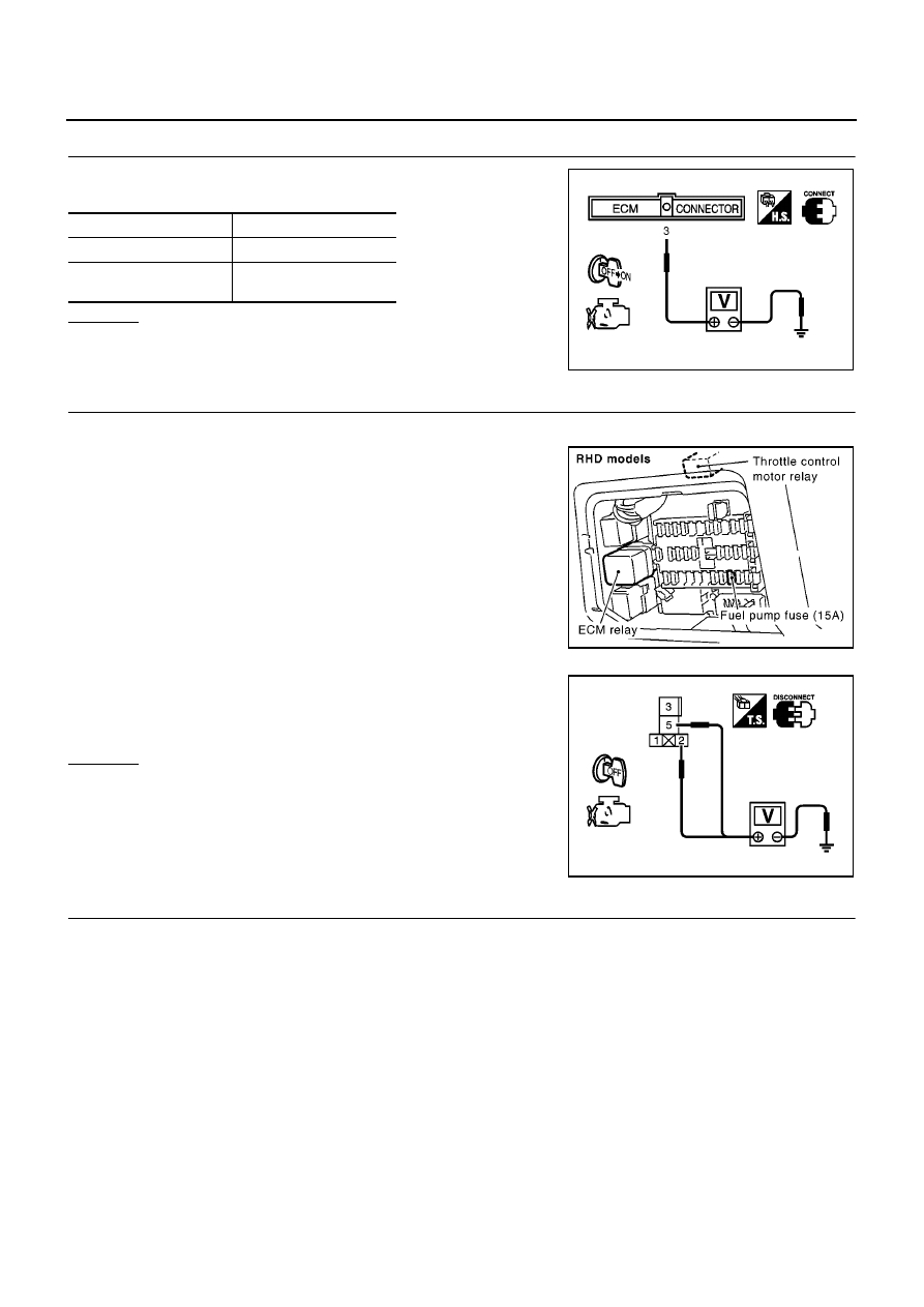
CHECK THROTTLE CONTROL MOTOR RELAY SIGNAL CIRCUIT

Check voltage between ECM terminal 3 and ground under the fol-
lowing conditions with CONSULT-II or tester.

OK or NG

OK

>> GO TO 10.

NG

>> GO TO 3.

3.

CHECK THROTTLE CONTROL MOTOR RELAY POWER SUPPLY CIRCUIT

1.

Turn ignition switch “OFF”.

2.

Disconnect throttle control motor relay.

3.

Check voltage between throttle control motor relay terminals 2, 5
and ground.

OK or NG

OK

>> GO TO 5.

NG

>> GO TO 4.

4.

DETECT MALFUNCTIONING PART

Check the following.

15A fuse

Harness for open or short between throttle control motor relay and fuse

>> Repair open circuit or short to ground or short to power in harness or connectors.

Ignition switch

Voltage

OFF

Approximately 0V

ON

Battery voltage

(11 - 14V)

MBIB0028E

MBIB0999E

Voltage: Battery voltage

PBIB0575E

DTC P1122 ELECTRIC THROTTLE CONTROL FUNCTION

EC-395

[QG (WITH EURO-OBD)]

C

D

E

F

G

H

I

J

K

L

M

A

EC

5.

CHECK THROTTLE CONTROL MOTOR RELAY INPUT SIGNAL CIRCUIT

1.

Disconnect ECM harness connector.

2.

Check harness continuity between ECM terminal 3 and throttle control motor relay terminal 3.
Refer to Wiring Diagram.

3.

Also check harness for short to ground and short to power.

OK or NG

OK

>> GO TO 7.

NG

>> GO TO 6.

6.

DETECT MALFUNCTIONING PART

Check the following.

Harness connectors E105, M10

Harness connectors M71, F45

Harness for open or short between ECM and throttle control motor relay

>> Repair open circuit or short to ground or short to power in harness or connectors.

7.

CHECK THROTTLE CONTROL MOTOR RELAY OUTPUT SIGNAL CIRCUIT

1.

Check continuity between ECM terminal 104 and throttle control motor relay terminal 1.
Refer to Wiring Diagram.

2.

Also check harness for short to ground and short to power.

OK or NG

OK

>> GO TO 9.

NG

>> GO TO 8.

8.

DETECT MALFUNCTIONING PART

Check the following.

Harness connectors E106, M11 (LHD models)

Harness connectors E145, M80 (RHD models)

Harness for open or short between ECM and throttle control motor relay

>> Repair open circuit or short to ground or short to power in harness or connectors.

9.

CHECK THROTTLE CONTROL MOTOR RELAY

Refer to

EC-397, "Component Inspection"

.

OK or NG

OK

>> GO TO 13.

NG

>> Replace throttle control motor relay.

Continuity should exist.

Continuity should exist.

EC-396

[QG (WITH EURO-OBD)]

DTC P1122 ELECTRIC THROTTLE CONTROL FUNCTION

10.

CHECK THROTTLE CONTROL MOTOR OUTPUT SIGNAL CIRCUIT FOR OPEN OR SHORT

1.

Turn ignition switch “OFF”.

2.

Disconnect electric throttle control actuator harness connector.

3.

Disconnect ECM harness connector.

4.

Check harness continuity between the following terminals.
Refer to Wiring Diagram.

5.

Also check harness for short to ground and short to power.

OK or NG

OK

>> GO TO 11.

NG

>> Repair open circuit or short to ground or short to power in harness or connectors.

11.

CHECK ELECTRIC THROTTLE CONTROL ACTUATOR VISUALLY

1.

Remove the intake air duct.

2.

Check if foreign matter is caught between the throttle valve and
the housing.

OK or NG

OK

>> GO TO 12.

NG

>> Remove the foreign matter and clean the electric throttle

control actuator inside.

12.

CHECK THROTTLE CONTROL MOTOR

Refer to

EC-397, "Component Inspection"

.

OK or NG

OK

>> GO TO 13.

NG

>> GO TO 14.

13.

CHECK INTERMITTENT INCIDENT

Refer to

EC-138, "TROUBLE DIAGNOSIS FOR INTERMITTENT INCIDENT"

.

OK or NG

OK

>> GO TO 14.

NG

>> Repair or replace harness or connectors.

14.

REPLACE ELECTRIC THROTTLE CONTROL ACTUATOR

1.

Replace the electric throttle control actuator.

2.

Perform

EC-49, "Throttle Valve Closed Position Learning"

.

3.

Perform

EC-49, "Idle Air Volume Learning"

.

>> INSPECTION END

Electric throttle control

actuator terminal

ECM terminal

Continuity

3

4

Should exist

5

Should not exist

6

4

Should not exist

5

Should exist

MBIB0100E

MBIB0107E

DTC P1122 ELECTRIC THROTTLE CONTROL FUNCTION

EC-397

[QG (WITH EURO-OBD)]

C

D

E

F

G

H

I

J

K

L

M

A

EC

Component Inspection

EBS00QP7

THROTTLE CONTROL MOTOR RELAY

1.

Apply 12V direct current between relay terminals 1 and 2.

2.

Check continuity between relay terminals 3 and 5.

3.

If NG, replace throttle control motor relay.

THROTTLE CONTROL MOTOR

1.

Disconnect electric throttle control actuator harness connector.

2.

Check resistance between terminals 3 and 6.

3.

If NG, replace electric throttle control actuator and go to next
step.

4.

Perform

EC-49, "Throttle Valve Closed Position Learning"

.

5.

Perform

EC-49, "Idle Air Volume Learning"

.

Remove and Installation

EBS00QP8

ELECTRIC THROTTLE CONTROL ACTUATOR

Refer to

EM-18, "INTAKE MANIFOLD"

.

Conditions

Continuity

12V direct current supply
between terminals 1 and 2

Yes

No current supply

No

PBIB0098E

Resistance: Approximately 1 - 15

[at 25

°

C (77

°

F)]

PBIB0095E


Content   ..  390  391  392  393   ..