Nissan Almera Tino V10. Manual - part 389
EC-382
[QG (WITH EURO-OBD)]
DTC P1065 ECM POWER SUPPLY
Specification data are reference values and are measured between each terminal and ground.
CAUTION:
Do not use ECM ground terminals when measuring input/output voltage. Doing so may result in dam-
age to the ECM's transistor. Use a ground other than ECM terminals, such as the ground.
Diagnostic Procedure
EBS00QOO
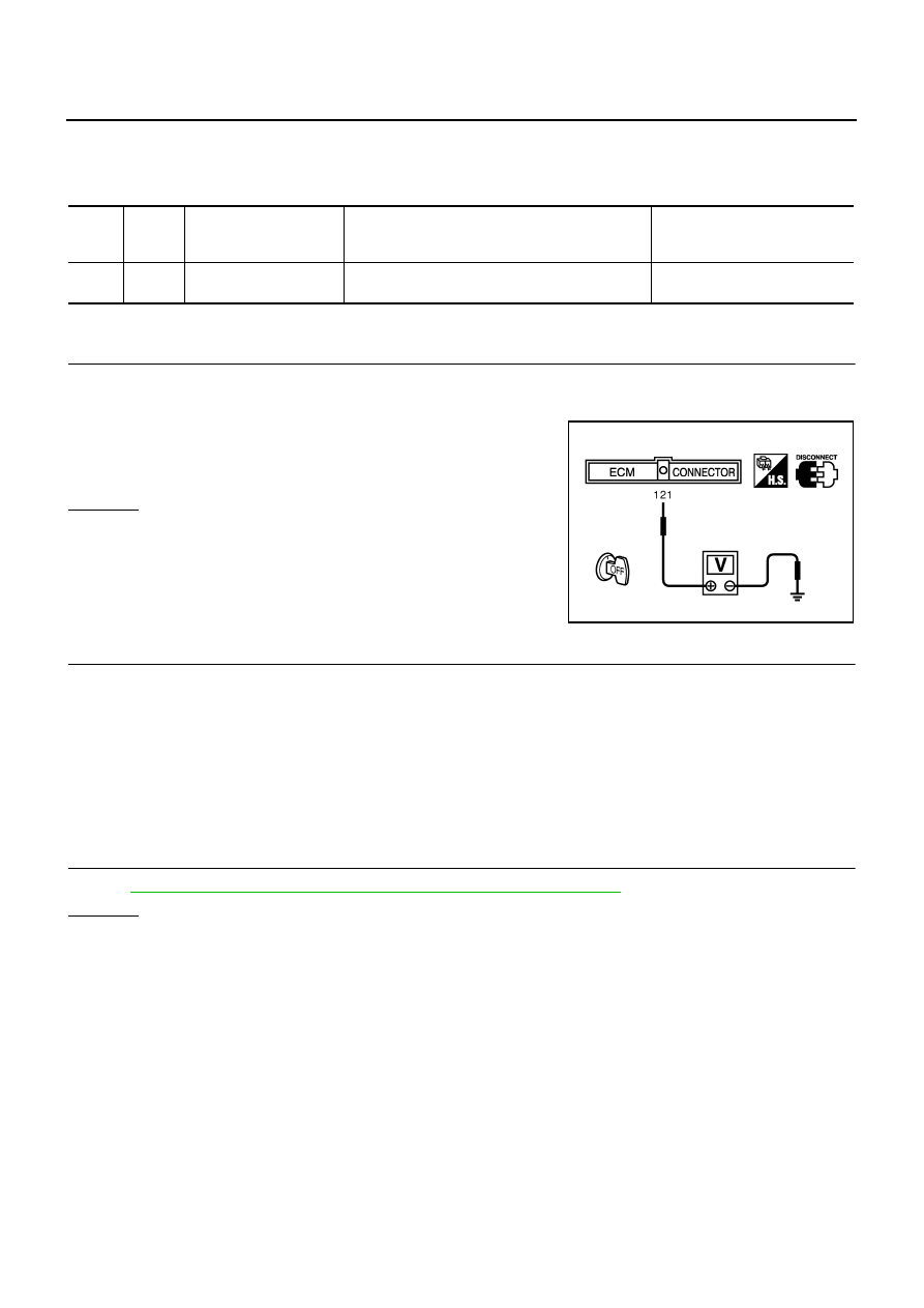
1.
CHECK ECM POWER SUPPLY
1.
Turn ignition switch “OFF”.
2.
Disconnect ECM harness connector.
3.
Check voltage between ECM terminal 121 and ground with
CONSULT-II or tester.
OK or NG
OK
>> GO TO 3.
NG
>> GO TO 2.
2.
DETECT MALFUNCTIONING PART
Check the following.
●
Harness connectors E106, M11 (LHD models)
●
Harness connectors E145, M80 (RHD models)
●
10A fuse
●
Harness for open or short between ECM and battery
>> Repair open circuit or short to ground or short to power in harness or connectors.
3.
CHECK INTERMITTENT INCIDENT
Refer to
EC-138, "TROUBLE DIAGNOSIS FOR INTERMITTENT INCIDENT"
.
OK or NG
OK
>> GO TO 4.
NG
>> Repair open circuit or short to ground or short to power in harness or connectors.
TER-
MINAL
NO.
WIRE
COLOR
ITEM
CONDITION
DATA (DC Voltage)
121
W/L
Power supply for ECM
(Buck-up)
[Ignition switch “OFF”]
BATTERY VOLTAGE
(11 - 14V)
Voltage: Battery voltage
MBIB0026E