Nissan Almera Tino V10. Manual - part 348


  Index      Nissan     Nissan Almera Tino V10 - Service Manual (2003 year)


Search            


Content   ..  346  347  348  349   ..


Nissan Almera Tino V10. Manual - part 348


EC-218

[QG (WITH EURO-OBD)]

DTC P0133, P0153, HO2S1 (A/T MODELS)

DTC P0133, P0153, HO2S1 (A/T MODELS)

PFP:22690

Component Description

EBS00QJY

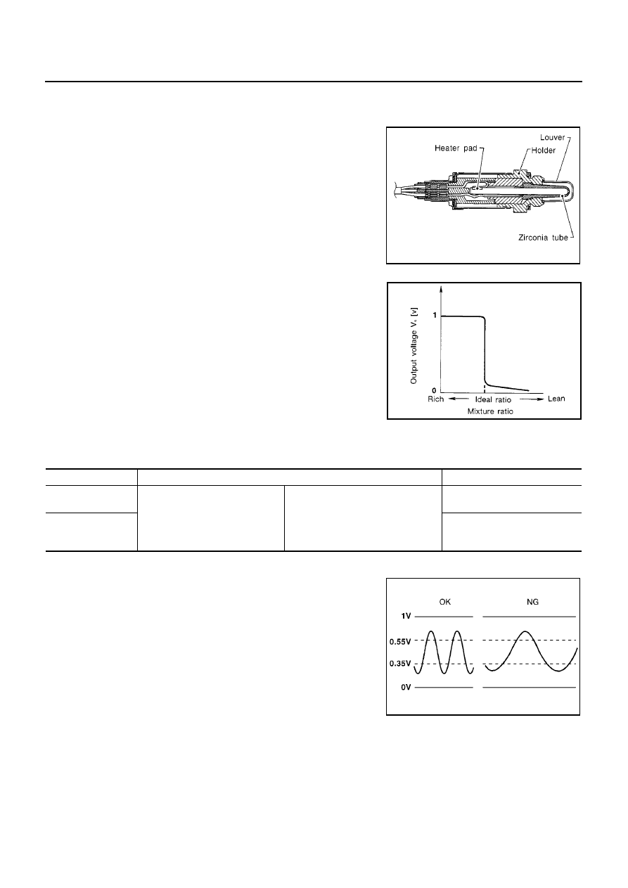
The heated oxygen sensor 1 is placed into the exhaust manifold. It
detects the amount of oxygen in the exhaust gas compared to the
outside air. The heated oxygen sensor 1 has a closed-end tube
made of ceramic zirconia. The zirconia generates voltage from
approximately 1V in richer conditions to 0V in leaner conditions. The
heated oxygen sensor 1 signal is sent to the ECM. The ECM adjusts
the injection pulse duration to achieve the ideal air-fuel ratio. The
ideal air-fuel ratio occurs near the radical change from 1V to 0V.

CONSULT-II Reference Value in Data Monitor Mode

EBS00QJZ

Specification data are reference values.

On Board Diagnosis Logic

EBS00QK0

To judge the malfunction of heated oxygen sensor 1, this diagnosis
measures response time of heated oxygen sensor 1 signal. The time
is compensated by engine operating (speed and load), fuel feedback
control constant, and heated oxygen sensor 1 temperature index.
Judgment is based on whether the compensated time (heated oxy-
gen sensor 1 cycling time index) is inordinately long or not.

SEF463R

SEF288D

MONITOR ITEM

CONDITION

SPECIFICATION

HO2S1 (B1)
HO2S1 (B2)

Engine: After warming up

Maintaining engine speed at 2,000
rpm

0 - 0.3V

←→

Approx. 0.6 - 1.0V

HO2S1 MNTR (B1)
HO2S1 MNTR (B2)

LEAN

←→

RICH

Changes more than 5 times dur-
ing 10 seconds.

SEF010V

DTC P0133, P0153, HO2S1 (A/T MODELS)

EC-219

[QG (WITH EURO-OBD)]

C

D

E

F

G

H

I

J

K

L

M

A

EC

DTC Confirmation Procedure

EBS00QK1

CAUTION:

Always drive vehicle at a safe speed.

NOTE:
If “DTC Confirmation Procedure” has been previously conducted, always turn ignition switch “OFF” and wait at
least 10 seconds before conducting the next test.

TESTING CONDITION:

Always perform at a temperature above

10

°

C (14

°

F).

Before performing the following procedure, confirm that battery voltage is more than 11V at idle.

WITH CONSULT-II

1.

Start engine and warm it up to normal operating temperature.

2.

Stop engine and wait at least 10 seconds.

3.

Turn ignition switch “ON” and select “HO2S1 (B1) P0133” or “HO2S1 (B2) P0153” of “HO2S1” in “DTC
WORK SUPPORT” mode with CONSULT-II.

4.

Touch “START”.

5.

Start engine and let it idle for at least 3 minutes.

NOTE:
Never raise engine speed above 3,200 rpm after this step. If
the engine speed limit is exceeded, return to step 5.

6.

When the following conditions are met, “TESTING” will be dis-
played on the CONSULT-II screen. Maintain the conditions con-
tinuously until “TESTING” changes to “COMPLETED”. (It will
take approximately 20 to 50 seconds.)

If “TESTING” is not displayed after 5 minutes, retry from
step 2.

DTC No.

Trouble diagnosis name

DTC detecting condition

Possible cause

P0133
0133
(Bank 1)

Heated oxygen sensor 1
circuit slow response

The response of the voltage signal from the
sensor takes more than the specified time.

Harness or connectors
(The sensor circuit is open or shorted.)

Heated oxygen sensor 1

Fuel pressure

Injectors

Intake air leaks

Exhaust gas leaks

PCV valve

Mass air flow sensor

P0153
0153
(Bank 2)

SEF338Z

ENG SPEED

1,900 - 3,100 rpm

Vehicle speed

More than 80 km/h (50 MPH)

B/FUEL SCHDL

3.7 - 7.8 msec

Selector lever

Suitable position

SEF339Z

EC-220

[QG (WITH EURO-OBD)]

DTC P0133, P0153, HO2S1 (A/T MODELS)

7.

Make sure that “OK” is displayed after touching “SELF-DIAG
RESULTS”. If “NG” is displayed, refer to

EC-224, "Diagnostic

Procedure"

.

Overall Function Check

EBS00QK2

Use this procedure to check the overall function of the heated oxygen sensor 1 circuit. During this check, a
DTC might not be confirmed.

WITH GST

1.

Start engine and warm it up to normal operating temperature.

2.

Set voltmeter probes between ECM terminal 35 [HO2S1(B1) signal] or 36 [HO2S1(B2) signal] and engine
ground.

3.

Check the following with engine speed held at 2,000 rpm con-
stant under no load.

The voltage fluctuates between 0 to 0.3V and 0.6 to 1.0V more
than 5 times within 10 seconds.

4.

If NG, go to

EC-224, "Diagnostic Procedure"

.

SEF658Y

1 time:

0 - 0.3V

0.6 - 1.0V

0 - 0.3V

2
times:

0 - 0.3V

0.6 - 1.0V

0 - 0.3V

0.6 - 1.0V

0 - 0.3V

MBIB0019E

DTC P0133, P0153, HO2S1 (A/T MODELS)

EC-221

[QG (WITH EURO-OBD)]

C

D

E

F

G

H

I

J

K

L

M

A

EC

Wiring Diagram

EBS00QK3

BANK 1

YEC444A


Content   ..  346  347  348  349   ..