Nissan Almera Tino V10. Manual - part 342


  Index      Nissan     Nissan Almera Tino V10 - Service Manual (2003 year)


Search            


Content   ..  340  341  342  343   ..


Nissan Almera Tino V10. Manual - part 342


EC-194

[QG (WITH EURO-OBD)]

DTC P0132 HO2S1 (M/T MODELS)

DTC Confirmation Procedure

EBS00QJC

NOTE:
If “DTC Confirmation Procedure” has been previously conducted, always turn ignition switch “OFF” and wait at
least 10 seconds before conducting the next test.

WITH CONSULT-II

1.

Start engine and warm it up to normal operating temperature.

2.

Turn ignition switch “OFF” and wait at least 10 seconds.

3.

Turn ignition switch “ON”.

4.

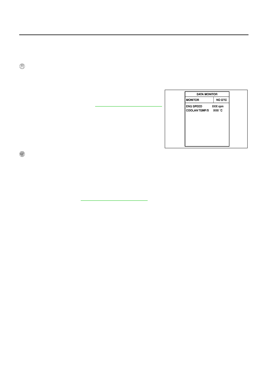
Select “DATA MONITOR” mode with CONSULT-II.

5.

Restart engine and let it idle for 2 minutes.

6.

If 1st trip DTC is detected, go to

EC-196, "Diagnostic Procedure"

.

WITH GST

1.

Start engine and warm it up to normal operating temperature.

2.

Turn ignition switch “OFF” and wait at least 10 seconds.

3.

Restart engine and let it idle for 2 minutes.

4.

Turn ignition switch “OFF” and wait at least 10 seconds.

5.

Restart engine and let it idle for 2 minutes.

6.

Select “MODE 3” with GST.

7.

If DTC is detected, go to

EC-196, "Diagnostic Procedure"

.

When using GST, “DTC Confirmation Procedure” should be performed twice as much as when
using CONSULT-II because GST cannot display MODE 7 (1st trip DTC) concerning this diagnosis.
Therefore, using CONSULT-II is recommended.

SEF174Y

DTC P0132 HO2S1 (M/T MODELS)

EC-195

[QG (WITH EURO-OBD)]

C

D

E

F

G

H

I

J

K

L

M

A

EC

Wiring Diagram

EBS00QJD

YEC443A

EC-196

[QG (WITH EURO-OBD)]

DTC P0132 HO2S1 (M/T MODELS)

Specification data are reference values and are measured between each terminal and ground.

CAUTION:

Do not use ECM ground terminals when measuring input/output voltage. Doing so may result in dam-
age to the ECM's transistor. Use a ground other than ECM terminals, such as the ground.

Diagnostic Procedure

EBS00QJE

1.

RETIGHTEN HEATED OXYGEN SENSOR 1

1.

Turn ignition switch “OFF”.

2.

Loosen and retighten heated oxygen sensor 1.

>> GO TO 2.

2.

CHECK HO2S1 GROUND CIRCUIT FOR OPEN AND SHORT

1.

Disconnect heated oxygen sensor 1 harness connector.

2.

Disconnect ECM harness connector.

3.

Check harness continuity between ECM terminal 74 and HO2S1
terminal 3.
Refer to Wiring Diagram.

4.

Also check harness for short to ground and short to power.

OK or NG

OK

>> GO TO 3.

NG

>> Repair open circuit or short to ground or short to power

in harness or connectors.

TERMI-

NAL

NO.

WIRE

COLOR

ITEM

CONDITION

DATA (DC Voltage)

35

W

Heated oxygen sensor 1

[Engine is running]

Warm-up condition

Engine speed is 2,000 rpm.

0 - Approximately 1.0V
(Periodically change)

74

B

Sensors' ground
(Heated oxygen sensor)

[Engine is running]

Idle speed

Approximately 0V

Tightening torque: 40 - 60 N·m (4.1 - 6.2 kg-m, 30 - 44 ft-lb)

MBIB0098E

Continuity should exist.

MBIB0091E

DTC P0132 HO2S1 (M/T MODELS)

EC-197

[QG (WITH EURO-OBD)]

C

D

E

F

G

H

I

J

K

L

M

A

EC

3.

CHECK HO2S1 INPUT SIGNAL CIRCUIT FOR OPEN AND SHORT

1.

Check harness continuity between ECM terminal 35 and HO2S1 terminal 2.
Refer to Wiring Diagram.

2.

Check harness continuity between ECM terminal 35 or HO2S1 terminal 2 and ground.
Refer to Wiring Diagram.

3.

Also check harness for short to power.

OK or NG

OK

>> GO TO 4.

NG

>> Repair open circuit or short to ground or short to power in harness or connectors.

4.

CHECK HO2S1 CONNECTOR FOR WATER

Check heated oxygen sensor 1 connectors for water.

OK or NG

OK

>> GO TO 5.

NG

>> Repair or replace harness or connectors.

5.

CHECK HEATED OXYGEN SENSOR 1

Refer to

EC-197, "Component Inspection"

.

OK or NG

OK

>> GO TO 6.

NG

>> Replace heated oxygen sensor 1.

6.

CHECK INTERMITTENT INCIDENT

Refer to

EC-138, "TROUBLE DIAGNOSIS FOR INTERMITTENT INCIDENT"

.

>> INSPECTION END

Component Inspection

EBS00QJF

HEATED OXYGEN SENSOR 1

With CONSULT-II

1.

Start engine and warm it up to normal operating temperature.

2.

Select “MANU TRIG” and adjust “TRIGGER POINT” to 100% in “DATA MONITOR” mode with CONSULT-
II.

3.

Select “HO2S1 (B1)” and “HO2S1 MNTR (B1)”.

4.

Hold engine speed at 2,000 rpm under no load during the follow-
ing steps.

5.

Touch “RECORD” on CONSULT-II screen.

Continuity should exist.

Continuity should not exist.

Water should not exist.

SEF646Y


Content   ..  340  341  342  343   ..