Nissan Almera Tino V10. Manual - part 226


  Index      Nissan     Nissan Almera Tino V10 - Service Manual (2003 year)


Search            


Content   ..  224  225  226  227   ..


Nissan Almera Tino V10. Manual - part 226


ATC-100

TROUBLE DIAGNOSIS

Sunload Sensor Circuit

EJS0037I

COMPONENT DESCRIPTION

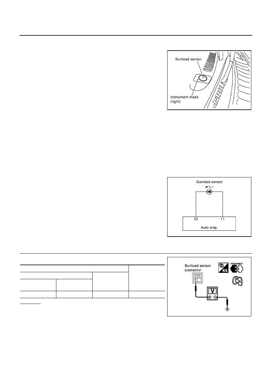
The sunload sensor is located on the instrument mask. It detects
sunload entering through windshield by means of a photo diode. The
sensor converts the sunload into a current value which is then input
into the auto amplifier.

SUNLOAD INPUT PROCESS

The auto amp. also includes a processing circuit which averages the variations in detected sunload over a
period of time. This prevents drastic swings in the A/C system operation due to small or quick variations in
detected sunload.
For example, consider driving along a road bordered by an occasional group of large trees. The sunload
detected by the sunload sensor will vary whenever the trees obstruct the sunlight. The processing circuit aver-
ages the detected sunload over a period of time, so that the (insignificant) effect of the trees momentarily
obstructing the sunlight does not cause any change in the A/C system operation. On the other hand, shortly
after entering a long tunnel, the system will recognize the change in sunload, and the system will react accord-
ingly.

DIAGNOSTIC PROCEDURE FOR SUNLOAD SENSOR

SYMPTOM: Sunload sensor circuit is open or shorted. (25 or

25) is

indicated on auto amp. as a result of conducting Self-diagnosis
STEP 2.)

1.

CHECK SUNLOAD SENSOR CIRCUIT BETWEEN SUNLOAD SENSOR AND GROUND

Disconnect sunload sensor harness connector.

OK or NG

OK

>> GO TO 2.

NG

>> GO TO 4.

RJIA2330E

RJIA0814E

Terminal

Voltage

(+)

(-)

Sunload sensor

connector

Terminal No. (Wire

color)

M105

1 (OR)

Ground

Approx. 5V

RJIA0563E

TROUBLE DIAGNOSIS

ATC-101

C

D

E

F

G

H

I

K

L

M

A

B

ATC

2.

CHECK SUNLOAD SENSOR CIRCUIT BETWEEN SUNLOAD SENSOR AND AUTO AMP.

Disconnect auto amp. harness connector.

OK or NG

OK

>> GO TO 3.

NG

>> Repair harness or connector.

3.

CHECK SUNLOAD SENSOR.

Refer to

ATC-100, "Sunload Sensor Circuit"

.

OK or NG

OK

>> 1. Replace auto amp.

2. Go to

ATC-42, "FUNCTION CONFIRMATION PROCEDURE"

and perform self-diagnosis

STEP-2. Confirm that code No. 20 is displayed.

NG

>> 1. Replace sunload sensor.

2. Go to

ATC-42, "FUNCTION CONFIRMATION PROCEDURE"

and perform self-diagnosis

STEP-2. Confirm that code No. 20 is displayed.

4.

CHECK SUNLOAD SENSOR CIRCUIT BETWEEN SUNLOAD SENSOR AND AUTO AMP.

Disconnect auto amp. harness connector.

OK or NG

OK

>> 1. Replace auto amp.

2. Go to

ATC-42, "FUNCTION CONFIRMATION PRO-

CEDURE"

and perform self-diagnosis STEP-2. Con-

firm that code No. 20 is displayed.

NG

>> Repair harness or connector.

Terminal

Continuity

(+)

(-)

Sunload sen-

sor connector

Terminal No.

(Wire color)

Auto amp.

connector

Terminal No.

(Wire color)

M105

2 (B/Y)

M110

11 (B/Y)

Yes

RJIA0815E

Terminal

Continuity

(+)

(-)

Sunload sen-

sor connector

Terminal No.

(Wire color)

Auto amp.

connector

Terminal No.

(Wire color)

M105

1 (OR)

M110

12 (OR)

Yes

RJIA0816E

ATC-102

TROUBLE DIAGNOSIS

COMPONENT INSPECTION
Sunload Sensor

Measure voltage between auto amp. terminal 12 (OR) and ground.
If NG, replace auto amp.

When checking sunload sensor, select a place where sun shines directly on it.

RJIA2331E

SHA930E

TROUBLE DIAGNOSIS

ATC-103

C

D

E

F

G

H

I

K

L

M

A

B

ATC

Intake Sensor Circuit

EJS0037J

COMPONENT DESCRIPTION
Intake Sensor

The intake sensor is located on the heater & cooling unit. It converts
temperature of air after it passes through the evaporator into a resis-
tance value which is then input to the auto amp.
After disconnecting intake sensor harness connector, measure resis-
tance between terminals 1 and 2 at sensor harness side, using the
table below.

If NG, replace intake sensor.

DIAGNOSTIC PROCEDURE FOR INTAKE SENSOR

SYMPTOM: Intake sensor circuit is open or shorted. (24 or

24) is

indicated on auto amp. as a result of conducting Self-diagnosis
STEP 2.

1.

CHECK INTAKE SENSOR CIRCUIT BETWEEN INTAKE SENSOR AND GROUND

Disconnect intake sensor harness connector.

OK or NG

OK

>> GO TO 2.

NG

>> GO TO 4.

Temperature

°

C (

°

F)

Resistance k

15 (5)

12.34

10 (14)

9.62

5 (23)

7.56

0 (32)

6.00

5 (41)

4.80

10 (50)

3.87

15 (59)

3.15

20 (68)

2.57

25 (77)

2.12

30 (86)

1.76

35 (95)

1.47

40 (104)

1.23

45 (113)

1.04

RJIA0166E

RHA056GA

Terminal

Voltage

(+)

(-)

Intake sensor

connector

Terminal No.

(Wire color)

M103

1 (OR/B)

Ground

Approx. 5V

RJIA0819E


Content   ..  224  225  226  227   ..