Nissan Almera Tino V10. Manual - part 211
ATC-40
TROUBLE DIAGNOSIS
10
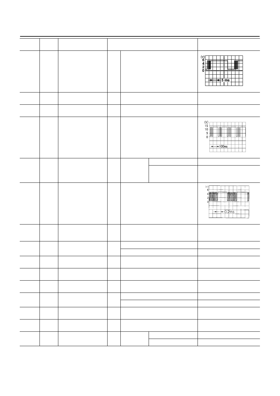
L/R
Multiplex communication
(Rx) signal
AV
→
A/C amp.
IGN
ON
-
11
B/Y
Sensor ground
IGN
ON
-
Approx. 0
12
OR
Sunload sensor
IGN
ON
-
-
17
PU/W
Water temperature sen-
sor signal
IGN
ON
Engine coolant temperature: Approx.
60
°
C
18
BR/W
Compressor feed back
signal
IGN
ON
A/C ON
-
Approx. 0
When refrigerant pres-
sure sensor connector is
disconnected.
Approx. 5
20
L
Multiplex communication
(CLK) signal
IGN
ON
-
21
G/Y
Power supply for mode
door, air mix door and
intake door motor
IGN
ON
-
Approx. 12
22
L/R
Compressor ON signal
IGN
ON
Compressor: ON
Approx. 0
Compressor: OFF
Approx. 5
24
B
Ground
IGN
ON
-
Approx. 0
26
R/B
Power supply for BATT
IGN
OFF
-
Approx. 12
27
Y/G
Power supply for IGN
IGN
ON
-
Approx. 12
29
LG/B
Fan ON signal
IGN
ON
Blower fan: ON
Approx. 0
Blower fan: OFF
Approx. 5
33
L/W
Power supply for ACC
IGN
ON
-
Approx. 12
34
L/B
Blower fan motor feed
back signal
IGN
ON
Fan speed: Manual 1st
Approx. 8
35
L/Y
Fan control amp. control
signal
IGN
ON
Fan speed:
Manual 1st - 4th speed
Approx. 2.5 - 3.5
Manual 5th speed
Approx. 9.0
TERMI-
NAL NO.
WIRE
COLOR
ITEM
CONDITION
Voltage
(V)
RJIA0213E
SKIA0056J
HAK0363D