Nissan Almera Tino V10. Manual - part 204
ATC-12
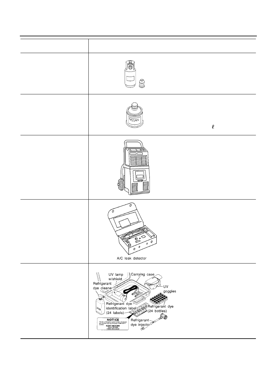
PREPARATION
Tool number
Tool name
Description
HFC-134a (R-134a) refrigerant
Container color: Light blue
Container marking: HFC-134a (R-
134a)
Fitting size: Thread size
●
Large container 1/2
″
-16 ACME
KLH00-PAGS0
Nissan A/C System Oil Type S
Type: Poly alkylene glycol oil (PAG),
type S
Application: HFC-134a (R-134a)
swash plate compressors (Nissan
only)
Lubricity: 40 m
(1.4 Imp fl oz.)
Recovery/Recycling/
Recharging equipment (ACR4)
Function: Refrigerant Recovery and
Recycling and Recharging
Electrical leak detector
Power supply:
DC 12V (Cigarette lighter)
(J-43926)
Refrigerant dye leak detection kit
Kit includes:
(J-42220)
Fluorescent dye leak detector
(J-41459)
HFC-134a (R-134a) dye injector
Use with J-41447, 1/4 ounce
bottle
(J-41447)
HFC-134a (R-134a) fluorescent
leak detection dye
(Box, of 24, 1/4 ounce bottles)
(J-43872)
Dye cleaner
Power supply:
DC 12V (Battery terminal)
S-NT196
S-NT197
RJIA0195E
SHA705EB
ZHA200H