Nissan Almera Tino V10. Manual - part 168


  Index      Nissan     Nissan Almera Tino V10 - Service Manual (2003 year)


Search            


Content   ..  166  167  168  169   ..


Nissan Almera Tino V10. Manual - part 168


AT-396

[ALL]

LINE PRESSURE SOLENOID VALVE

3.

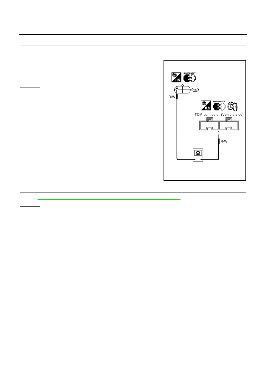
CHECK POWER SOURCE CIRCUIT

1.

Turn ignition switch to “OFF” position.

2.

Check resistance between terminal 4 and TCM harness connector terminal 1.

If NG, check harness for short to ground and short to power.

3.

Reinstall any part removed.

OK or NG

OK

>> GO TO 4

NG

>> Repair open circuit or short to ground or short to power

in harness or connectors.

4.

CHECK DTC

Perform

AT-393, "SELF-DIAGNOSIS CODE CONFIRMATION PROCEDURE"

.

OK or NG

OK

>> INSPECTION END

NG

>> 1. Perform TCM input/output signal inspection.

2. If NG, recheck TCM pin terminals for damage or loose connection with harness connector.

Resistance: Approx. 0

MCIA0087E

LINE PRESSURE SOLENOID VALVE

AT-397

[ALL]

D

E

F

G

H

I

J

K

L

M

A

B

AT

Component Inspection

ECS009BT

LINE PRESSURE SOLENOID VALVE

For removal, refer to

AT-410, "Control Valve Assembly and Accumulators"

.

Resistance Check

Check resistance between two terminals.

Operation Check

Check solenoid valve by listening for its operating sound while
applying battery voltage to the terminal and ground.

Solenoid valve

Terminal No.

Resistance

(Approx.)

Line pressure
solenoid valve

4

Ground

2.5 - 5

MCIA0088E

MCIA0089E

AT-398

[ALL]

LINE PRESSURE SOLENOID VALVE

DROPPING RESISTOR

Check resistance between two terminals.

Resistance: 10 - 15

MCIA0090E

CAN COMMUNICATION LINE

AT-399

[ALL]

D

E

F

G

H

I

J

K

L

M

A

B

AT

CAN COMMUNICATION LINE

PFP:31940

Description

ECS009BU

CAN (Controller Area Network) is a serial communication line for real time application. It is an on-vehicle mul-
tiplex communication line with high data communication speed and excellent error detection ability. Many elec-
tronic control units are equipped onto a vehicle, and each control unit shares information and links with other
control units during operation (not independent). In CAN communication, control units are connected with 2
communication lines (CAN H line, CAN L line) allowing a high rate of information transmission with less wiring.
Each control unit transmits/receives data but selectively reads required data only.

TCM TERMINALS AND REFERENCE VALUE

Remarks: Specification data are reference values.

*: This terminal is connected to the ECM.

On Board Diagnosis Logic

ECS009BV

**: A/T COMM LINE means CAN communication line.

Self-Diagnosis Code Confirmation Procedure

ECS009BW

After the repair, perform the following procedure to confirm the malfunction is eliminated.

WITH CONSULT-II

1.

Turn ignition switch “ON”.

2.

Select “DATA MONITOR” mode for “A/T” with CONSULT-II.

3.

Wait at least 6 seconds or start engine and wait for at least 6
seconds.

4.

If DTC is detected, go to

AT-401, "Diagnostic Procedure"

.

WITHOUT CONSULT-II

1.

Turn ignition switch “ON”.

2.

Wait at least 6 seconds or start engine and wait at least 6 sec-
onds.

3.

Perform self-diagnosis.
Refer to

AT-252, "Diagnostic Procedure Without CONSULT-II"

.

4.

If DTC is detected, go to

AT-401, "Diagnostic Procedure"

.

Termi-

nal No.

Wire color

Item

Condition

Judgement

standard

(Approx.)

5

L

CAN (H)

6

R

CAN (L)

Diagnostic trouble code

Malfunction is detected when...

Check items (Possible cause)

: A/T COMM LINE**

The ECM-AT communication line is open
or shorted.

Harness or connectors
(The solenoid circuit is open or shorted.)

Line pressure solenoid valve

: 11th judgement flicker

SAT014K

MCIA0118E


Content   ..  166  167  168  169   ..