Nissan Almera Tino V10. Manual - part 136


  Index      Nissan     Nissan Almera Tino V10 - Service Manual (2003 year)


Search            


Content   ..  134  135  136  137   ..


Nissan Almera Tino V10. Manual - part 136


AT-268

[EXC.F/EURO-OBD]

TROUBLE DIAGNOSIS — BASIC INSPECTION

JUDGEMENT OF LINE PRESSURE TEST
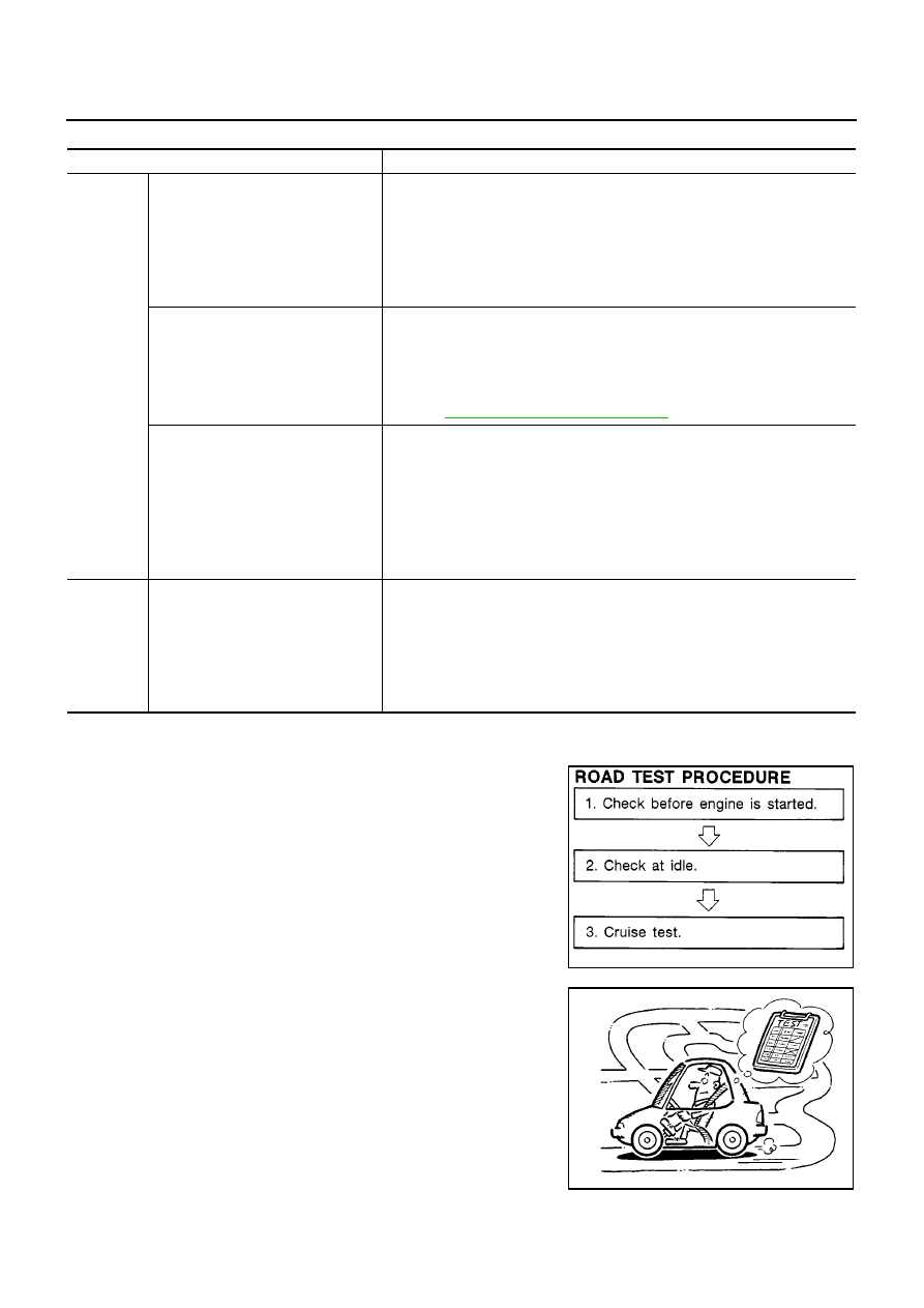
Road Test

ECS009A1

DESCRIPTION

The purpose of the test is to determine overall performance of A/
T and analyze causes of problems.

The road test consists of the following three parts:

1.

Check before engine is started

2.

Check at idle

3.

Cruise test

Before road test, familiarize yourself with all test procedures and
items to check.

Conduct tests on all items until specified symptom is found.
Troubleshoot items which check out No Good after road test.
Refer to the following items.

Judgement

Suspected parts

At idle

Line pressure is low in all positions.

Oil pump wear

Control piston damage

Pressure regulator valve or plug sticking

Spring for pressure regulator valve damaged

Fluid pressure leakage between oil strainer and pressure regulator valve

Clogged strainer

Line pressure is low in particular posi-
tion.

Fluid pressure leakage between manual valve and particular clutch

For example, line pressure is:

Low in “R” and “1” positions, but

Normal in “D” and “2” positions.

Therefore, fluid leakage exists at or around low and reverse brake circuit.

Refer to

AT-18, "CLUTCH AND BAND CHART"

.

Line pressure is high.

Maladjustment of throttle position sensor

A/T fluid temperature sensor damaged

Line pressure solenoid valve sticking

Short circuit of line pressure solenoid valve circuit

Pressure modifier valve sticking

Pressure regulator valve or plug sticking

Open in dropping resistor circuit

At stall
speed

Line pressure is low.

Maladjustment of throttle position sensor

Line pressure solenoid valve sticking

Short circuit of line pressure solenoid valve circuit

Pressure regulator valve or plug sticking

Pressure modifier valve sticking

Pilot valve sticking

SAT786A

SAT496G

TROUBLE DIAGNOSIS — BASIC INSPECTION

AT-269

[EXC.F/EURO-OBD]

D

E

F

G

H

I

J

K

L

M

A

B

AT

ON BOARD DIAGNOSTIC SYS-

TEM DESCRIPTION

TROUBLE DIAGNOSES FOR

SYMPTOMS

Except for
Euro-OBD

AT-246, "ON BOARD DIAG-

NOSTIC SYSTEM DESCRIP-

TION"

to

AT-252, "Diagnostic

Procedure Without CONSULT-

II"

AT-312, "1. O/D OFF Indicator

Lamp Does Not Come On"

to

AT-

337, "21. TCM Self-diagnosis

Does Not Activate (PNP & Over-

drive Control Switches, and

Throttle Position Sensor Circuit

Checks)"

AT-270

[EXC.F/EURO-OBD]

TROUBLE DIAGNOSIS — BASIC INSPECTION

1. CHECK BEFORE ENGINE IS STARTED

1.

CHECK O/D OFF INDICATOR LAMP

1.

Park vehicle on flat surface.

2.

Turn ignition switch to “OFF” position.

3.

Move selector lever to “P” position.

4.

Set overdrive control switch to “ON” position.

5.

Turn ignition switch to “ON” position. (Do not start engine.)

6.

Does O/D OFF indicator lamp come on for about 2 seconds?

Yes or No

Yes

>> GO TO 2

No

>> Stop ROAD TEST. GO TO

AT-312, "1. O/D OFF Indica-

tor Lamp Does Not Come On"

.

2.

CHECK O/D OFF INDICATOR LAMP

Does O/D OFF indicator lamp flicker for about 8 seconds?

Yes or No

Yes

>> Perform self-diagnosis and check NG items on the

DIAGNOSTIC WORKSHEET. Refer to

AT-258

and

AT-

252, "SELF-DIAGNOSTIC PROCEDURE (WITHOUT
CONSULT-II)"

.

No

>> 1. Turn ignition switch to “OFF” position.

2. Perform self-diagnosis and note NG items.

Refer to

AT-252, "SELF-DIAGNOSTIC PROCEDURE

(WITHOUT CONSULT-II)"

.

3. GO TO

AT-271, "2. CHECK AT IDLE"

.

SAT774B

MCIA0066E

MCIA0066E

TROUBLE DIAGNOSIS — BASIC INSPECTION

AT-271

[EXC.F/EURO-OBD]

D

E

F

G

H

I

J

K

L

M

A

B

AT

2. CHECK AT IDLE

1.

CHECK ENGINE START

1.

Park vehicle on flat surface.

2.

Turn ignition switch to “OFF” position.

3.

Move selector lever to “P” or “N” position.

4.

Turn ignition switch to “START” position.

5.

Is engine started?

Yes or No

Yes

>> GO TO 2

No

>>

Mark the box on the DIAGNOSTIC WORKSHEET.

GO TO

AT-313, "2. Engine Cannot Be Started In “P”

and “N” Position"

.

Continue ROAD TEST. Refer to

AT-268, "Road Test"

.

2.

CHECK ENGINE START

1.

Turn ignition switch to “OFF” position.

2.

Move selector lever to “D”, “1”, “2” or “R” position.

3.

Turn ignition switch to “START” position.

4.

Is engine started?

Yes or No

Yes

>>

Mark the box on the DIAGNOSTIC WORKSHEET.

GO TO

AT-313, "2. Engine Cannot Be Started In “P”

and “N” Position"

.

Continue ROAD TEST. Refer to

AT-268, "Road Test"

.

No

>> GO TO 3

3.

CHECK VEHICLE MOVE

1.

Turn ignition switch to “OFF” position.

2.

Move selector lever to “P” position.

3.

Release parking brake.

4.

Push vehicle forward or backward.

5.

Does vehicle move when it is pushed forward or backward?

Yes or No

Yes

>>

Mark the box on the DIAGNOSTIC WORKSHEET.

GO TO

AT-313, "3. In “P” Position, Vehicle Moves

Forward Or Backward When Pushed"

.

Continue ROAD TEST. Refer to

AT-268, "Road Test"

.

No

>> GO TO 4

SAT769B

SAT770B

SAT768B

SAT796A


Content   ..  134  135  136  137   ..