Nissan Almera Tino V10. Manual - part 50


  Index      Nissan     Nissan Almera Tino V10 - Service Manual (2003 year)


Search            


Content   ..  48  49  50  51   ..


Nissan Almera Tino V10. Manual - part 50


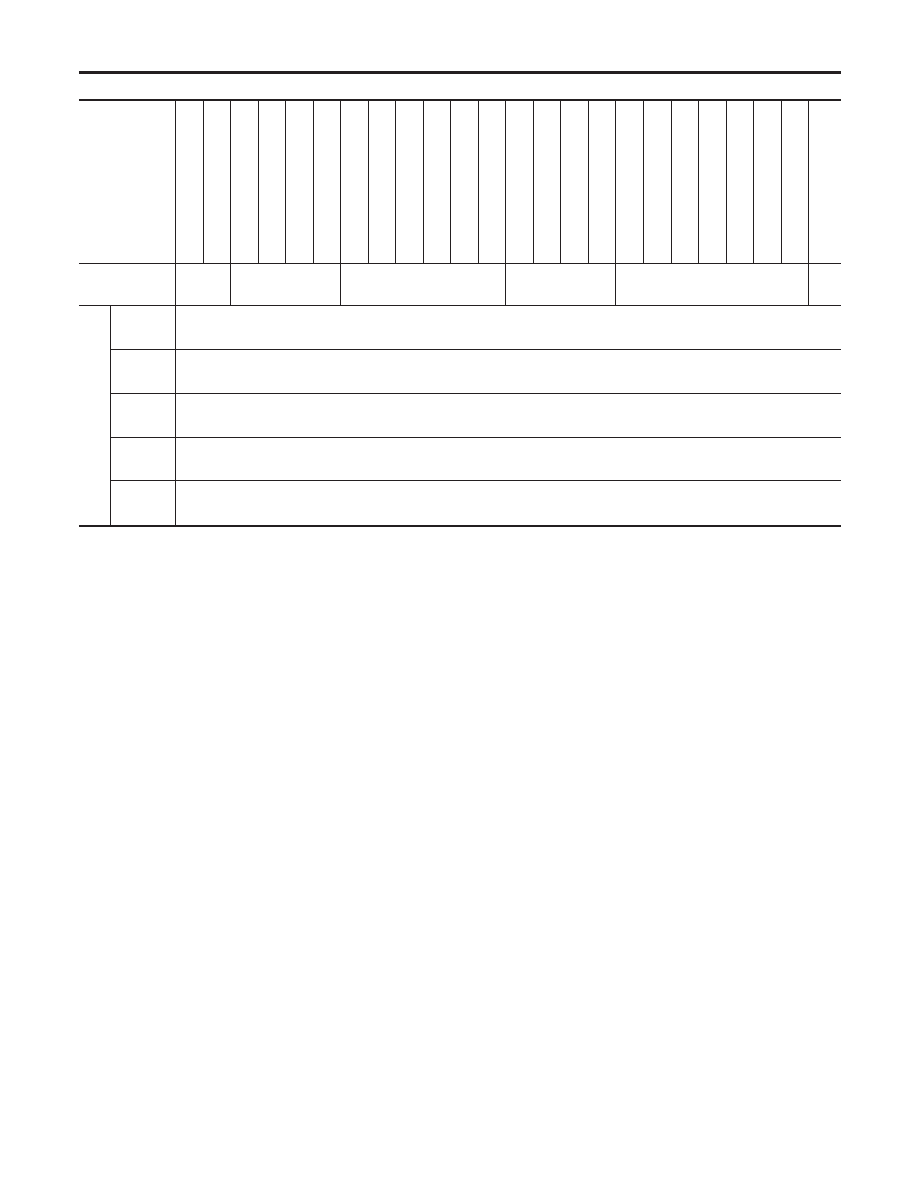
Fig. 6 INITIAL CHARGING CURRENT SETTING AND CHARGING TIME (Quick charge)

BATTERY

TYPE

28B19R(L)

34B19R(L)

46B24R(L)

55B24R(L)

50D23R(L)

079

[YUASA

type

code]

55D23R(L)

65D26R(L)

80D26R(L)

025

[YUASA

type

code]

027

[YUASA

type

code]

063

[YUASA

type

code]

065

[YUASA

type

code]

075

[YUASA

type

code]

067

[YUASA

type

code]

096

[YUASA

type

code]

096L

[YUASA

type

code]

010S

[YUASA

type

code]

75D31R(L)

95D31R(L)

1

15D31R(L)

1

10D26R(L)

95E41R(L)

130E41R(L)

CURRENT [A]

10 (A)

15 (A)

20 (A)

25 (A)

30 (A)

40

(A)

CONVER

TED

SPECIFIC

GRA

VITY

1.100 -

1.130

2.5 hours

1.130 -

1.160

2.0 hours

1.160 -

1.190

1.5 hours

1.190 -

1.220

1.0 hours

Above

1.220

0.75 hours (45 min.)

I

Check battery type and determine the specified current using the table shown above.

I

After starting charging, adjustment of charging current is not necessary.

CAUTION:

I

Do not use quick charge method on a battery whose specific gravity is less than 1.100.

I

Set initial charging current to value specified in Fig. 6. If charger is not capable of producing
specified current value, set its charging current as close to that value as possible.

I

Keep battery away from open flame while it is being charged.

I

When connecting charger, connect leads first, then turn on charger. Do not turn on charger first,
as this may cause a spark.

I

Be careful of a rise in battery temperature because a large current flow is required during quick-
charge operation.
If battery temperature rises above 60°C (140°F), stop charging. Always charge battery when its
temperature is below 60°C (140°F).

I

Do not exceed the charging time specified in Fig. 6, because charging battery over the charging
time can cause deterioration of the battery.

BATTERY

Battery Test and Charging Chart (Cont’d)

SC-12

System Description

NLSC0004

M/T MODELS

NLSC0004S01

Power is supplied at all times

I

through 40A fusible link (letter J, located in the fuse and fusible link box)

I

to ignition switch terminal 1.

With the ignition switch in START position, power is supplied

I

from ignition switch terminal 5

I

to smart entrance control unit terminal 59

I

from smart entrance control unit terminal 58

I

to starter motor harness connector terminal 1.

The starter motor plunger closes and provides a closed circuit between the battery and starter motor. The
starter motor is grounded to the engine block. With power and ground supplied, cranking occurs and the engine
starts.

A/T MODELS

NLSC0004S02

Power is supplied at all times

I

through 40A fusible link (letter J, located in the fuse and fusible link box)

I

to ignition switch terminal 1.

With the ignition switch in the START position, power is supplied

I

from ignition switch terminal 5

I

to park/neutral position relay terminal 5.

With the ignition switch ON or START position, power is supplied

I

through 10A fuse [No. 20, located in the fuse block (J/B)]

I

to park/neutral position (PNP) relay terminal 1.

With the selector lever in the P or N position, ground is supplied

I

to park/neutral position relay terminal 2 through the park/neutral position switch

I

from body ground F10.

Then park/neutral position relay is energized and power is supplied

I

from park/neutral position relay terminal 3

I

to starter motor harness connector terminal 1.

The starter motor plunger closes and provides a closed circuit between the battery and starter motor. The
starter motor is grounded to the engine block. With power and ground supplied, cranking occurs and the engine
starts.

GI

MA

EM

LC

EC

FE

CL

MT

AT

AX

SU

BR

ST

RS

BT

HA

EL

IDX

STARTING SYSTEM

System Description

SC-13

Wiring Diagram — START —

NLSC0005

M/T MODELS

NLSC0005S06

YEL052E

STARTING SYSTEM

Wiring Diagram — START —

SC-14

A/T MODELS

NLSC0005S07

YEL053E

GI

MA

EM

LC

EC

FE

CL

MT

AT

AX

SU

BR

ST

RS

BT

HA

EL

IDX

STARTING SYSTEM

Wiring Diagram — START — (Cont’d)

SC-15


Content   ..  48  49  50  51   ..