Nissan Almera Tino V10. Manual - part 19
SMA803A
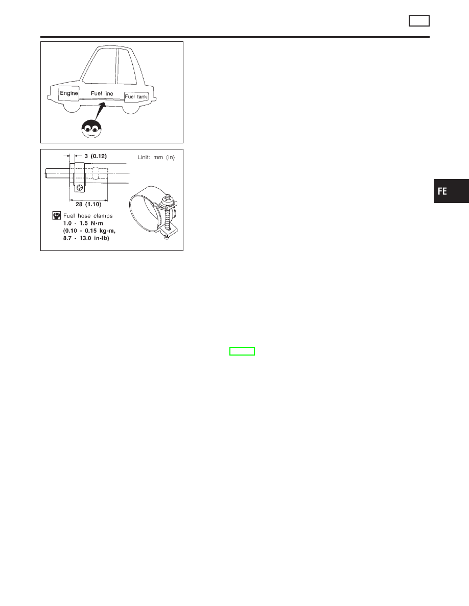
Checking Fuel Lines
NLFE0009
Inspect fuel lines and tank for improper attachment, leaks, cracks,
damage, loose connections, chafing or deterioration.
If necessary, repair or replace faulty parts.
MMA104A
CAUTION:
Tighten high-pressure rubber hose clamp so that clamp end is
3 mm (0.12 in) from hose end.
Tightening torque specifications are the same for all rubber
hose clamps.
Ensure that screw does not contact adjacent parts.
Removal and Installation
NLFE0004
WARNING:
When replacing fuel line parts, be sure to observe the following.
I
Put a “CAUTION: FLAMMABLE” sign in workshop.
I
Be sure to furnish workshop with a CO
2
fire extinguisher.
I
Do not smoke while servicing fuel system. Keep open flames and sparks away from work area.
CAUTION:
I
Before removing fuel line parts, carry out the following procedures:
a) Put drained fuel in an explosion-proof container and put the lid on securely.
b) Release fuel pressure from fuel line. Refer to EC-47 (QG), “Fuel Pressure Release”.
c) Disconnect battery ground cable.
I
Always replace O-ring and clamps with new ones.
I
Do not kink or twist tubes when they are being installed.
I
Do not tighten hose clamps excessively to avoid damaging hoses.
I
After installing tubes, run engine and check for fuel leaks at connections.
GI
MA
EM
LC
EC
CL
MT
AT
AX
SU
BR
ST
RS
BT
HA
SC
EL
IDX
FUEL SYSTEM
QG
Checking Fuel Lines
FE-5