Nissan GT-R (2007-2014 year). STEERING SYSTEM / TRANSAXLE & TRANSMISSION. Service Manual - part 2
HYDRAULIC LINE
ST-17
< REMOVAL AND INSTALLATION >
C
D
E
F
H
I
J
K
L
M
A
B
ST
N
O
P
HYDRAULIC LINE
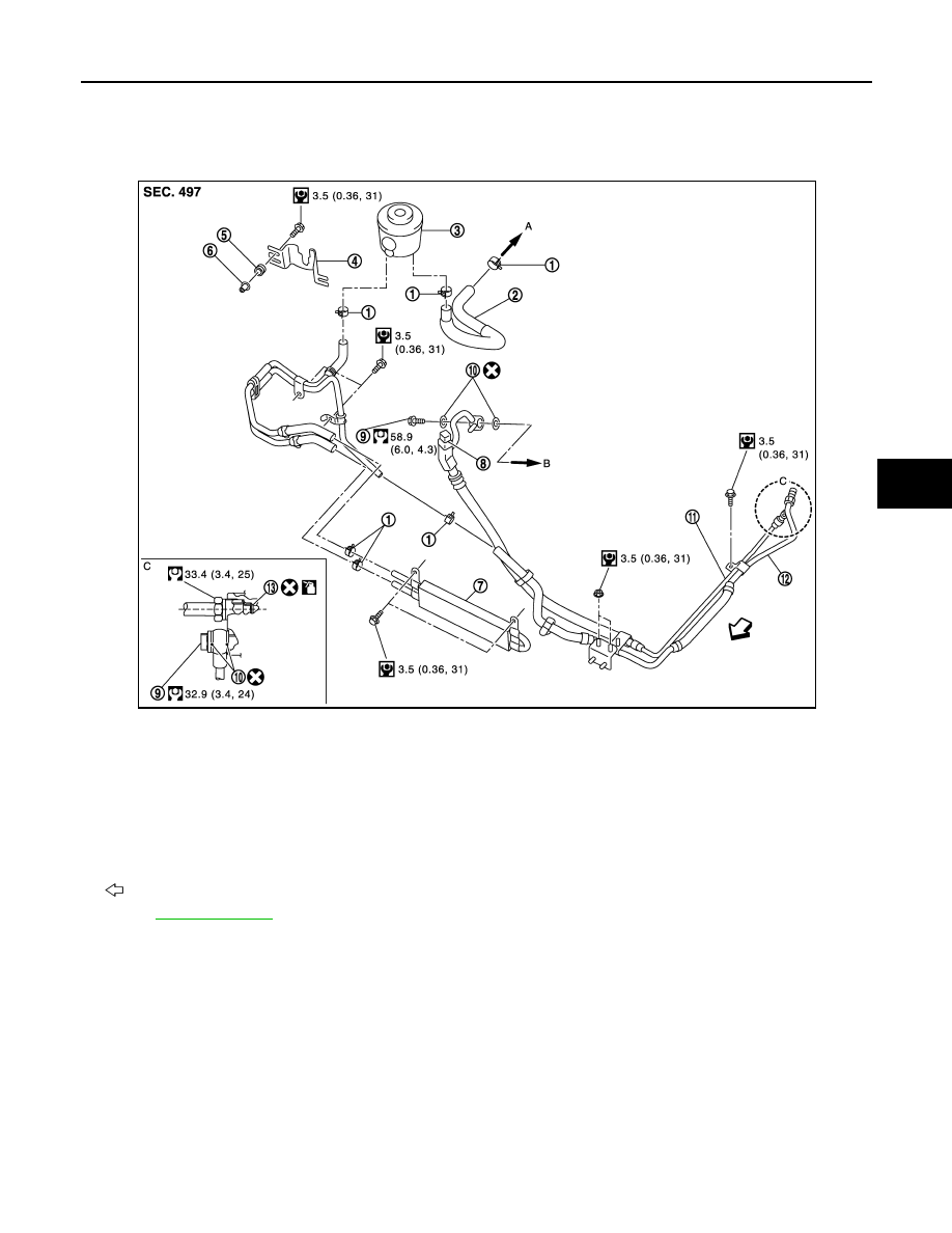
Exploded View
INFOID:0000000009160114
1.
Clamp
2.
Suction hose
3.
Reservoir tank
4.
Reservoir tank bracket
5.
Bushing
6.
Collar
7.
Oil cooler
8.
Pressure sensor
9.
Eye bolt
10. Copper washer
11.
High pressure piping
12. Low pressure piping
13. O-ring
A.
To power steering oil pump suction
piping.
B.
To power steering oil pump.
: Vehicle front
Refer to
NNGIA0037GB
2014 GT-R