Nissan GT-R (2007-2014 year). METER, WARNING LAMP & INDICATOR. Service Manual - part 3


  Index      Manuals     Nissan GT-R (2007-2014 year). METER, WARNING LAMP & INDICATOR. Service Manual


Search            copyright infringement  


Content      ..     1      2      3      4      ..


Nissan GT-R (2007-2014 year). METER, WARNING LAMP & INDICATOR. Service Manual - part 3


MWI

METER SYSTEM

MWI-33

< SYSTEM DESCRIPTION >

C

D

E

F

G

H

I

J

K

L

M

B

A

O

P

LOW BRAKE FLUID WARNING

Control Outline

• The combination meter receives the brake fluid level switch signal from the brake fluid level switch.
• Based on the received brake fluid level switch signal, the combination meter displays the low brake fluid

warning.

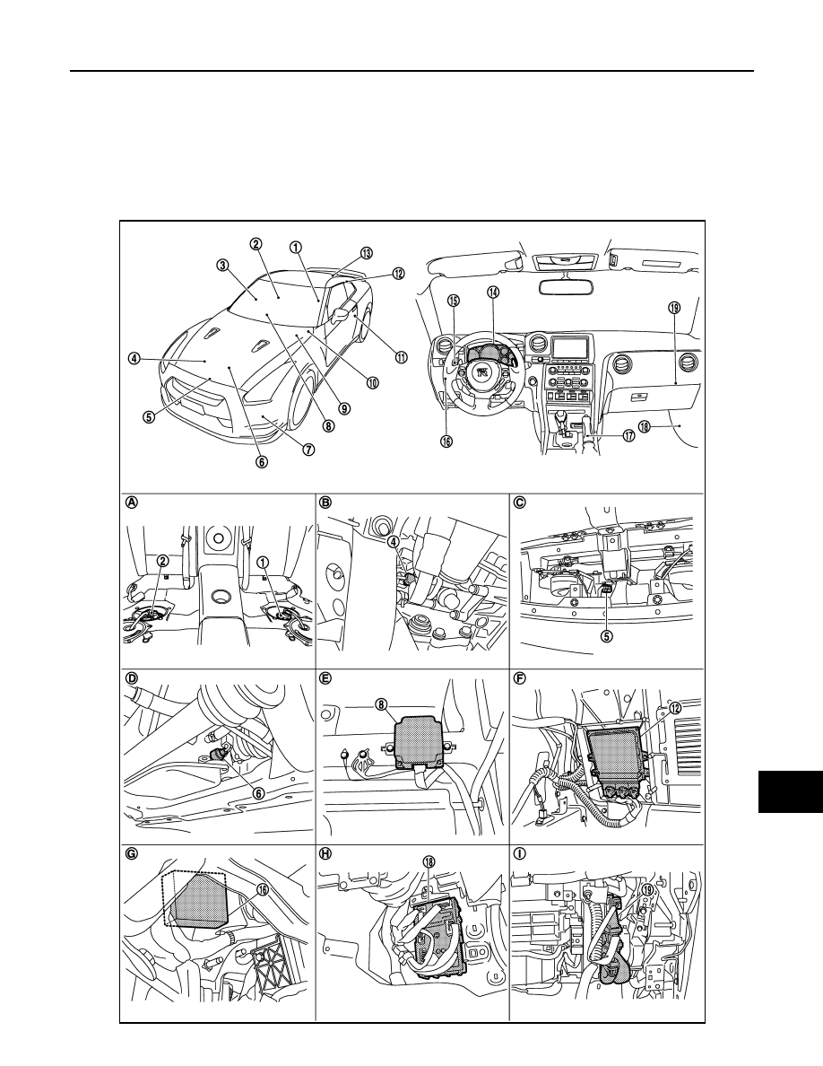
INFORMATION DISPLAY : Component Parts Location

INFOID:0000000009189328

JPNIA1142ZZ

Revision: 2012 November

2014 GT-R

MWI-34

< SYSTEM DESCRIPTION >

METER SYSTEM

INFORMATION DISPLAY : Component Description

INFOID:0000000009189329

1.

Fuel level sensor unit
(Sub)

2.

Fuel level sensor unit
(Main)

3.

Door switch (passenger side)

4.

Oil pressure sensor

5.

Ambient sensor

6.

Oil level sensor

7.

Washer level switch

8.

AWD control unit

9.

Brake fluid level switch

10. ABS actuator and electric unit (con-

trol unit)

11. Door switch (driver side)

12. TCM

13. Trunk switch

14. Combination meter

15. Combination switch (Lighting switch)

16. Low tire pressure warning control unit 17. Parking brake

18. BCM

19. ECM

A.

Under rear seat

B.

Right side of engine

C.

Radiator core support (center)

D.

Oil pan LH upper

E.

Front RH seat under

F.

Trunk room left back

G.

Lower instrument panel LH

H.

Dashboard side lower (passenger 
seat side)

I.

Glove box assembly back

Unit

Description

Combination meter

Based on each received signal from each unit, switch, and sensor, controls the information dis-
play.

Fuel level sensor unit

Detects the fuel level in fuel tank using the fuel level sensor unit, and transmits the fuel gauge 
signal to the combination meter.

Oil pressure sensor

Detects the oil pressure of engine oil, and transmits the oil pressure sensor signal to the com-
bination meter.

ECM

Transmits the following signals to the combination meter via CAN communication.

• Engine speed signal

• Fuel consumption monitor signal

• Engine status signal

• ASCD status signal

ABS actuator and electric unit (con-
trol unit)

Transmits the following signals to the combination meter via CAN communication.

• Vehicle speed signal

• ABS warning display signal

• VDC warning display signal

BCM

Transmits the signals received from each unit to the combination meter via CAN communica-
tion.

TCM

Transmits the following signals to the combination meter via CAN communication.

• Shift lever position check display signal

• Shift lever position warning display signal

• Transmission oil high temperature warning 

display signal

• Transmission clutch high temperature 

warning display signal

• Transmission system warning display sig-

nal

• Transmission system check display signal

AWD control unit

Transmits the following signals to the combination meter via CAN communication.

• AWD clutch high temperature warning dis-

play signal

• Front/rear tire size discrepancy warning dis-

play signal

• AWD system warning display signal

Low tire pressure warning control 
unit

Transmits the following signals to the combination meter via CAN communication.

• Run-flat tire warning display signal

• Low tire pressure warning display signal

• Tire pressure monitoring system warning 

display signal

Meter control switch

Transmits the following signals to the combination meter.

• Enter switch signal

• Select switch signal

Brake fluid level switch

Transmits the brake fluid level switch signal to the combination meter.

Parking brake switch

Transmits the parking brake switch signal to the combination meter.

Oil level sensor

Transmits the oil level sensor signal to the combination meter.

Revision: 2012 November

2014 GT-R

MWI

METER SYSTEM

MWI-35

< SYSTEM DESCRIPTION >

C

D

E

F

G

H

I

J

K

L

M

B

A

O

P

UP-SHIFT INDICATOR

UP-SHIFT INDICATOR : System Diagram

INFOID:0000000009189330

UP-SHIFT INDICATOR : System Description

INFOID:0000000009189331

• The combination meter receives the engine speed signal from ECM and the shift position signal (manual

mode range) from TCM via CAN communication, and illuminates/turns off/blinks the up-shift indicator.

• The engine speed at which the up-shift indicator is illuminated/turned off/blinked can be set with the setting

function of information display.

- OFF: All of the up-shift indicators do not illuminate.
- 3,000 to 6,300 rpm: Engine speed can be set at which the up-shift indicator (green) is illuminated. 
- AUTO: Up-shift indicator (green) does not illuminate. The up-shift indicator (yellow) and up-shift indicator

(red) is turned on/off according to the set value.

UP-SHIFT INDICATOR (GREEN)

• Using the setting function of information display, the up-shift warning speed can be set.
• The up-shift indicator (green) is illuminated/turned off/blinked according to the engine speed.
- OFF: If the actual engine speed is lower than the arbitrarily set engine speed, which is 3,000 to 6,300 rpm

set by the setting function of information display, by 500 rpm or more, the up-shift warning lamp is turned
OFF. 
Also, while the up-shift indicator (green) is blinking or illuminated, if the actual engine speed becomes lower
than the arbitrarily set engine speed by 600 rpm or more, the up-shift warning lamp is turned OFF.

- Blink: If the actual engine speed is lower than the arbitrarily set engine speed by 500 rpm or more, the up-

shift indicator (green) is blinked. 

- ON: When the actual engine speed exceeds the arbitrarily set engine speed, the up-shift indicator (green) is

illuminated.
Also, while the up-shift indicator (green) is blinking or illuminated, if the actual engine speed becomes lower
than the arbitrarily set engine speed by 100 rpm or more, the up-shift indicator is blinked. 

UP-SHIFT INDICATOR (YELLOW)

The up-shift indicator (yellow) is turned ON/OFF according to the engine speed.
• OFF: When the engine speed is less than 6,300 rpm, the up-shift indicator (yellow) does not illuminate.

Also, while the up-shift indicator (yellow) is illuminated, when the engine speed becomes 6,200 rpm or lower,
the up-shift indicator (yellow) is turned OFF.

• ON: When the engine speed becomes 6,300 rpm or more, the up-shift indicator (yellow) is illuminated.

UP-SHIFT INDICATOR (RED)

The up-shift indicator (red) is turned ON/OFF according to the engine speed.
• OFF: When the engine speed is less than 6,800 rpm, the up-shift indicator (red) does not illuminate.

Washer level switch

Transmits the washer level switch signal to the combination meter.

Ambient sensor

Detects the ambient air temperature, and transmits the ambient sensor signal to the combina-
tion meter.

Unit

Description

JPNIA1148GB

Revision: 2012 November

2014 GT-R

MWI-36

< SYSTEM DESCRIPTION >

METER SYSTEM

Also, while the up-shift indicator (red) is illuminated, when the engine speed becomes 6,700 rpm or lower,
the up-shift indicator (red) is turned OFF.

• ON: When the engine speed becomes 6,800 rpm or more, the up-shift indicator (red) is illuminated.

UP-SHIFT INDICATOR : Component Parts Location

INFOID:0000000009189332

JPNIA1142ZZ

Revision: 2012 November

2014 GT-R

MWI

METER SYSTEM

MWI-37

< SYSTEM DESCRIPTION >

C

D

E

F

G

H

I

J

K

L

M

B

A

O

P

UP-SHIFT INDICATOR : Component Description

INFOID:0000000009189333

1.

Fuel level sensor unit
(Sub)

2.

Fuel level sensor unit
(Main)

3.

Door switch (passenger side)

4.

Oil pressure sensor

5.

Ambient sensor

6.

Oil level sensor

7.

Washer level switch

8.

AWD control unit

9.

Brake fluid level switch

10. ABS actuator and electric unit (con-

trol unit)

11. Door switch (driver side)

12. TCM

13. Trunk switch

14. Combination meter

15. Combination switch (Lighting switch)

16. Low tire pressure warning control unit 17. Parking brake

18. BCM

19. ECM

A.

Under rear seat

B.

Right side of engine

C.

Radiator core support (center)

D.

Oil pan LH upper

E.

Front RH seat under

F.

Trunk room left back

G.

Lower instrument panel LH

H.

Dashboard side lower (passenger 
seat side)

I.

Glove box assembly back

Unit

Description

Combination meter

Using the signals received from each unit and switch, controls the shift position indicator.

ECM

Transmits the engine speed signal to the combination meter via CAN communication.

TCM

Transmits the shift position signal (manual mode range) to the combination meter via CAN com-
munication.

Meter control switch

Transmits the following signals to the combination meter.

• Enter switch signal

• Select switch signal

Revision: 2012 November

2014 GT-R

MWI-38

< SYSTEM DESCRIPTION >

DIAGNOSIS SYSTEM (METER)

DIAGNOSIS SYSTEM (METER)

Diagnosis Description

INFOID:0000000009189334

SELF-DIAGNOSIS MODE

Using the self-diagnosis mode function, the combination meter can check the drive circuit of each meter
(speedometer, tachometer, engine coolant temperature gauge, and fuel gauge), dot matrix (odo/trip meter,
information display), and the LCD function of segment (shift position indicator).

OPERATION PROCEDURE

1.

Turn the ignition switch ON, and switch the tripmeter to “trip A” or “trip B”.
NOTE:
If the diagnosis function is activated with “trip A” displayed, the mileage on “trip A” is reset to “0000.0”.
(The same way for “trip B”.)

2.

Turn the ignition switch OFF.

3.

While pressing the trip A/B reset switch (1), turn the ignition
switch ON again.

4.

Check that the tripmeter displays “0000.0”. 

5.

Press the trip A/B reset switch at least 3 times (within 7 seconds
after the ignition switch is turned ON).

6.

The combination meter self-diagnosis mode starts.
• On the information display (1), the dots of the dot matrix blink

alternately.

• Pointers of speedometer, tachometer, and engine coolant tem-

perature gauge return to zero, and all of the segments of shift
position indicator illuminate.

NOTE:
• If the self diagnosis mode of combination meter does not start, check the combination meter power sup-

ply and ground circuit. When everything is normal, replace the combination meter.

• If any section of the dot matrix on information display or of the segment in shift position indicator does

not illuminate, replace the combination meter.

NNNIA0019ZZ

NNNIA0086ZZ

Revision: 2012 November

2014 GT-R

MWI

DIAGNOSIS SYSTEM (METER)

MWI-39

< SYSTEM DESCRIPTION >

C

D

E

F

G

H

I

J

K

L

M

B

A

O

P

7.

When the trip A/B reset switch is pressed, (while the trip A/B reset switch is pressed) each meter oper-
ates.

NOTE:
If any meter does not operate, replace the combination meter.
The figure is reference.

JPNIA1266ZZ

Revision: 2012 November

2014 GT-R

MWI-40

< DTC/CIRCUIT DIAGNOSIS >

POWER SUPPLY AND GROUND CIRCUIT

DTC/CIRCUIT DIAGNOSIS

POWER SUPPLY AND GROUND CIRCUIT

COMBINATION METER

COMBINATION METER : Diagnosis Procedure

INFOID:0000000009189335

1.

CHECK FUSES

Check that the following fuses are not blown:

Is the inspection result normal?

YES

>> GO TO 2.

NO

>> Replace the fuse with a new one after repairing the applicable circuit.

2.

CHECK POWER SUPPLY CIRCUIT

Check the voltage between the combination meter harness connector terminals and the ground. 

Is the inspection result normal?

YES

>> GO TO 3.

NO

>> Repair the harness between the fuse and the combination meter. 

3.

CHECK GROUND CIRCUIT

1.

Turn the ignition switch OFF.

2.

Disconnect the combination meter connector.

3.

Check for continuity between the combination meter harness connector terminals and the ground. 

Is the inspection result normal?

YES

>> INSPECTION END

NO

>> Repair the harnesses or connectors.

Power source

Fuse No.

Battery

11

Ignition switch ON or START

4

Terminal No.

Signal name

Ignition switch

Voltage

1

Battery power supply

OFF

Battery voltage

2

Ignition signal

ON

Battery voltage

Combination meter

Ground

Continuity

Connector

Terminal

M53

3

Existed

5

Revision: 2012 November

2014 GT-R

MWI

FUEL LEVEL SENSOR SIGNAL CIRCUIT

MWI-41

< DTC/CIRCUIT DIAGNOSIS >

C

D

E

F

G

H

I

J

K

L

M

B

A

O

P

FUEL LEVEL SENSOR SIGNAL CIRCUIT

Description

INFOID:0000000009189336

Detects the fuel level in fuel tank using the fuel level sensor unit, and transmits the fuel level sensor signal to
the combination meter.

Diagnosis Procedure

INFOID:0000000009189337

1.

CHECK FUEL LEVEL SENSOR UNIT (SUB) CIRCUIT

1.

Turn the ignition switch OFF.

2.

Disconnect the connectors of combination meter and fuel level sensor unit (sub).

3.

Check for continuity between the combination meter harness connector and the fuel level sensor unit
(sub) harness connector. 

4.

Check for continuity between the combination meter harness connector and the ground. 

Is the inspection result normal?

YES

>> GO TO 2.

NO

>> Repair the harnesses or connectors.

2.

CHECK FUEL LEVEL SENSOR UNIT (MAIN-SUB) CIRCUIT

1.

Disconnect fuel level sensor unit and fuel pump (main) connector.

2.

Check for continuity between the fuel level sensor unit (sub) harness connector and the fuel level sensor
unit and fuel pump (main) harness connector. 

3.

Check for continuity between the fuel level sensor unit (sub) harness connector and the ground. 

Is the inspection result normal?

YES

>> GO TO 3.

NO

>> Repair the harnesses or connectors.

3.

CHECK FUEL LEVEL SENSOR UNIT AND FUEL PUMP (MAIN) CIRCUIT

1.

Check for continuity between the fuel level sensor unit and fuel pump (main) harness connector and the
combination meter harness connector. 

Combination meter

Fuel level sensor unit (sub)

Continuity

Connector

Terminal

Connector

Terminal

M53

38

B27

1

Existed

Combination meter

Ground

Continuity

Connector

Terminal

M53

38

Not existed

Fuel level sensor unit (sub)

Fuel level sensor unit and fuel pump 

(main)

Continuity

Connector

Terminal

Connector

Terminal

B27

2

B225

2

Existed

Fuel level sensor unit (sub)

Ground

Continuity

Connector

Terminal

B27

2

Not existed

Fuel level sensor unit and fuel pump 

(main)

Combination meter

Continuity

Connector

Terminal

Connector

Terminal

B225

3

M53

18

Existed

Revision: 2012 November

2014 GT-R

MWI-42

< DTC/CIRCUIT DIAGNOSIS >

FUEL LEVEL SENSOR SIGNAL CIRCUIT

2.

Check for continuity between the fuel level sensor unit and fuel pump (main) harness connector and the
ground. 

Is the inspection result normal?

YES

>> Replace combination meter. Refer to 

MWI-68, "Removal and Installation"

.

NO

>> Repair the harnesses or connectors.

Fuel level sensor unit and fuel pump 

(main)

Ground

Continuity

Connector

Terminal

B225

3

Not existed

Revision: 2012 November

2014 GT-R

MWI

METER CONTROL SWITCH SIGNAL CIRCUIT

MWI-43

< DTC/CIRCUIT DIAGNOSIS >

C

D

E

F

G

H

I

J

K

L

M

B

A

O

P

METER CONTROL SWITCH SIGNAL CIRCUIT

Description

INFOID:0000000009189338

Transmits the following signals to the combination meter.

Diagnosis Procedure

INFOID:0000000009189339

1.

CHECK METER CONTROL SWITCH INPUT SIGNAL

1.

Turn the ignition switch ON.

2.

Measure voltage between the following terminals of the combination meter.

Is the inspection result normal?

YES

>> INSPECTION END

NO

>> GO TO 2.

2.

CHECK METER CONTROL SWITCH SIGNAL CIRCUIT

1.

Turn the ignition switch OFF.

2.

Disconnect the connectors of combination meter and meter control switch.

3.

Check for continuity between the combination meter harness connector terminal and the meter control
switch harness connector. 

4.

Check for continuity between the combination meter harness connector and the ground. 

• Illumination control switch signal (+) 

• Illumination control switch signal (–)

• Trip A/B reset switch signal

• Select switch signal

• Enter switch signal

Terminal 

No.

Condition

Voltage

(Approx.)

23 – 6

When 

 switch is pressed

0 V

Other than the above

5 V

24 – 6

When 

 switch is pressed

0 V

Other than the above

5 V

25 – 6

When trip A/B reset switch is pressed

0 V

Other than the above

5 V

26 – 6

When enter switch is pressed

0 V

Other than the above

5 V

27 – 6

When select switch is pressed

0 V

Other than the above

5 V

Combination meter

Meter control switch

Continuity

Connector

Terminal

Connector

Terminal

M53

6

M54

2

Existed

23

3

24

1

25

8

26

6

27

7

Revision: 2012 November

2014 GT-R

MWI-44

< DTC/CIRCUIT DIAGNOSIS >

METER CONTROL SWITCH SIGNAL CIRCUIT

Is the inspection result normal?

YES

>> INSPECTION END

NO

>> Repair the harnesses or connectors.

Component Inspection

INFOID:0000000009189340

1.

UNIT INSPECTION OF METER CONTROL SWITCH

1.

Turn the ignition switch OFF.

2.

Disconnect the meter control switch connector.

3.

Check the continuity of meter control switch.

Is the inspection result normal?

YES

>> INSPECTION END

NO

>> Replace the meter control switch.

Combination meter

Ground

Continuity

Connector

Terminal

M53

6

Not existed

23

24

25

26

27

Terminal No.

Operation and status

Continuity

6

2

Press the enter switch

Existed

Other than the above

Not existed

7

2

Press the select switch

Existed

Other than the above

Not existed

8

2

Press the trip A/B reset switch.

Existed

Other than the above

Not existed

3

2

Press the 

 switch

Existed

Other than the above

Not existed

1

2

Press the 

 switch

Existed

Other than the above

Not existed

Revision: 2012 November

2014 GT-R

MWI

OIL PRESSURE SENSOR SIGNAL CIRCUIT

MWI-45

< DTC/CIRCUIT DIAGNOSIS >

C

D

E

F

G

H

I

J

K

L

M

B

A

O

P

OIL PRESSURE SENSOR SIGNAL CIRCUIT

Description

INFOID:0000000009189341

Detects the engine oil pressure and transmits the oil pressure sensor signal to the combination meter.

Diagnosis Procedure

INFOID:0000000009189342

1.

CHECK OIL PRESSURE SENSOR CIRCUIT

1.

Turn the ignition switch OFF.

2.

Disconnect the connectors of combination meter and oil pressure sensor.

3.

Check for continuity between the combination meter harness connector and the oil pressure sensor har-
ness connector. 

4.

Check for continuity between the combination meter harness connector and the ground. 

Is the inspection result normal?

YES

>> INSPECTION END

NO

>> Repair the harnesses or connectors.

Component Inspection

INFOID:0000000009189343

1.

CHECK OIL PRESSURE SENSOR

Check the voltage between the combination meter terminal 35 and the ground. 

Is the inspection result normal?

YES

>> INSPECTION END

NO

>> Replace the oil pressure switch.

Combination meter

Oil pressure sensor

Continuity

Connector

Terminal

Connector

Terminal

M53

34

E255

1

Existed

M53

35

E255

2

Existed

M53

14

E255

3

Existed

Combination meter

Ground

Continuity

Connector

Terminal

M53

34

Not existed

M53

35

Not existed

M53

14

Not existed

Condition

Measuring condition

Voltage (V)

Engine stop

Ignition switch ON

Approx. 1

Engine running

Oil pressure is at 500 kPa

Approx. 3

Revision: 2012 November

2014 GT-R

MWI-46

< DTC/CIRCUIT DIAGNOSIS >

PARKING BRAKE SWITCH SIGNAL CIRCUIT

PARKING BRAKE SWITCH SIGNAL CIRCUIT

Description

INFOID:0000000009189344

Transmits the parking brake switch signal to the combination meter.

Diagnosis Procedure

INFOID:0000000009189345

1.

CHECK COMBINATION METER INPUT SIGNAL

1.

Turn the ignition switch ON.

2.

Check the voltage between the combination meter harness connector and the ground. 

Is the inspection result normal?

YES

>> INSPECTION END

NO

>> GO TO 2.

2.

CHECK PARKING BRAKE SWITCH SIGNAL CIRCUIT

1.

Turn the ignition switch OFF.

2.

Disconnect the connectors of combination meter and parking brake switch.

3.

Check for continuity between the combination meter harness connector and the parking brake switch har-
ness connector. 

4.

Check for continuity between the combination meter harness connector and the ground. 

Is the inspection result normal?

YES

>> INSPECTION END

NO

>> Repair the harnesses or connectors.

Component Inspection

INFOID:0000000009189346

1.

CHECK PARKING BRAKE SWITCH

1.

Turn the ignition switch OFF.

2.

Disconnect the parking brake switch connector.

3.

Check for continuity between the parking brake switch connector and the ground. 

YES

>> INSPECTION END

Probe

Measuring condition

Voltage

(Approx.)

(+)

(-)

Combination meter

Connector

Terminal

Ground

Parking brake operated

0 V

M53

31

Parking brake released

5 V

Combination meter

Parking brake switch

Continuity

Connector

Terminal

Connector

Terminal

M53

31

M132

1

Existed

Combination meter

Ground

Continuity

Connector

Terminal

M53

31

Not existed

Parking brake switch

Measuring condition

Continuity

(+)

(-)

1

Ground

Parking brake applied

Existed

Parking brake released

Not exist

Revision: 2012 November

2014 GT-R

MWI

PARKING BRAKE SWITCH SIGNAL CIRCUIT

MWI-47

< DTC/CIRCUIT DIAGNOSIS >

C

D

E

F

G

H

I

J

K

L

M

B

A

O

P

NO

>> Replace the parking brake switch.

Revision: 2012 November

2014 GT-R

MWI-48

< DTC/CIRCUIT DIAGNOSIS >

WASHER LEVEL SWITCH SIGNAL CIRCUIT

WASHER LEVEL SWITCH SIGNAL CIRCUIT

Description

INFOID:0000000009189347

When the washer fluid in washer tank is less than the specified level, and washer level switch is turned ON,
the washer level switch transmits the washer level switch signal to the combination meter.

Diagnosis Procedure

INFOID:0000000009189348

1.

CHECK COMBINATION METER INPUT SIGNAL

1.

Turn the ignition switch ON.

2.

Check the voltage between the combination meter harness connector and the ground. 

Is the inspection result normal?

YES

>> INSPECTION END

NO

>> GO TO 2.

2.

CHECK WASHER LEVEL SWITCH CIRCUIT

1.

Turn the ignition switch OFF.

2.

Disconnect the connectors of combination meter and washer level switch.

3.

Check for continuity between the combination meter harness connector and the washer level switch har-
ness connector. 

4.

Check for continuity between the combination meter harness connector and the ground. 

Is the inspection result normal?

YES

>> INSPECTION END

NO

>> Repair the harnesses or connectors.

Component Inspection

INFOID:0000000009189349

1.

CHECK WASHER LEVEL SWITCH

1.

Turn the ignition switch OFF.

2.

Disconnect the washer level switch connector.

3.

Check the washer level switch.

Is the inspection result normal?

YES

>> INSPECTION END

Probe

Measuring condition

Voltage

(Approx.)

(+)

(-)

Combination meter

Connector

Terminal

Ground

Washer level switch ON

0 V

M53

33

Washer level switch OFF

5 V

Combination meter

Washer level switch

Continuity

Connector

Terminal

Connector

Terminal

M53

33

E30

1

Existed

Combination meter

Ground

Continuity

Connector

Terminal

M53

33

Not existed

Terminal

Washer level switch

Continuity

1 - 2

ON

Existed

OFF

Not existed

Revision: 2012 November

2014 GT-R


Content      ..     1      2      3      4      ..